SDM-IO16 16 Channel Input/Output Expansion Module Revision: 4/09 C o p y r i g h t © 2 0 0 2 - 2 0 0 9 C a m p b e l l S c i e n t i f i c , I n c .
Warranty and Assistance The SDM-IO16 16 CHANNEL INPUT/OUTPUT EXPANSION MODULE is warranted by CAMPBELL SCIENTIFIC, INC. to be free from defects in materials and workmanship under normal use and service for twelve (12) months from date of shipment unless specified otherwise. Batteries have no warranty. CAMPBELL SCIENTIFIC, INC.'s obligation under this warranty is limited to repairing or replacing (at CAMPBELL SCIENTIFIC, INC.'s option) defective products.
IMPORTANT – Please Read First Datalogger Instruction 188 – Software Requirements 1. PC208W Datalogger Support Software NOTE PC208W support of SDM-IO16 Instruction 188 requires replacement of some PC208W files Datalogger Instruction 188 for the SDM-IO16 was developed after the release of PC208W version 3.3. Campbell Scientific will not release another version of PC208W but instead will offer the next generation datalogger support software which is LoggerNet.
2. CR23X and CR10X Operating System Requirements NOTE Use of SDM-IO16 Instruction 188 requires newer datalogger operating systems for the CR23X and CR10X. The following table lists the datalogger operating systems required for support of Instruction 188. To determine which operating system is presently installed in a datalogger, use the *B mode. See your datalogger manual for a detailed description. Campbell Scientific Datalogger Required Operating System Version --Listed version or later-- CR10X 1.
SDM-IO16 Table of Contents PDF viewers note: These page numbers refer to the printed version of this document. Use the Adobe Acrobat® bookmarks tab for links to specific sections. 1. Introduction..................................................................1 2. Specifications ..............................................................2 2.1 2.2 2.3 2.4 General .....................................................................................................2 Port Specifications (Output Mode).....
SDM-IO16 Table of Contents Appendices A. General Principles of Pulse and Frequency Measurements .................................................... A-1 A.1 A.2 A.3 A.4 A.5 Introduction......................................................................................... A-1 Frequency and Duty Cycle Measurement Range ................................ A-1 Resolution of Frequency Measurements ............................................. A-2 Resolution of Duty Cycle Measurements...........................
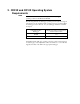
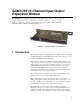
SDM-IO16 16 Channel Input/Output Expansion Module The SDM-IO16 (see Figure 1) is a synchronously addressed peripheral. It has 16 ports that can be configured for input or output which expand the number of control ports of the datalogger. It is fully compatible with Campbell Scientific’s CR800, CR850, CR1000, CR3000, CR5000, CR10X, and CR23X dataloggers. FIGURE 1. SDM-IO16 (with mounting brackets) 1.
SDM-IO16 16 Channel Input/Output Expansion Module to sixteen SDM-IO16s may be addressed, making it possible to control a maximum of 256 ports from the first three datalogger control ports. The SDM-IO16 is supplied with two removable mounting brackets that attach to the ends of the unit, as shown in Figure 1. NOTE The full functions and support for the error checked communications protocol require an operating system for the datalogger and Edlog template files that post-dates March 2002.
SDM-IO16 16 Channel Input/Output Expansion Module Mounting: Mounting brackets have two holes at 225 mm nominal spacing. Mounting screws and plastic inserts suitable for use with Campbell Scientific enclosures are also supplied. Weight: 350 g (including brackets) EMC status: Complies with EN61326:1997 Total SDM cable length: 6 m maximum recommended 2.2 Port Specifications (Output Mode) Output voltage (no load): Output ON/HI, Nominal 5 V (Minimum 4.5 V) Output OFF/LO, Nominal 0 V (Maximum 0.
SDM-IO16 16 Channel Input/Output Expansion Module Minimum frequency: a frequency of 0 Hz is measured if there are less than two high-to-low signal transitions in the measurement interval. Minimum pulse width: a pulse must stay high or low for a minimum of 244 μsec for a change of state or pulse to be counted. Switch debounce timing: with the default settings a switch between the input and G must remain closed for 3.17 msec and then remain open for 3.17 msec, to be counted as a closure2.
SDM-IO16 16 Channel Input/Output Expansion Module 5V 100 K To internal logic 510 Ω 33 Ω From sensor 5.6 V OV OV a) Input biasing and protection 0.6 V Drop Output 550 Ω 0.33 Ω 510 Ω 5 V, 0Ω Output V b) Output set ON c) Output set OFF FIGURE 2. Simplified Equivalent Port Circuits 3. Power Considerations For most applications, especially for pulse counting or status inputs, it is more normal to use the datalogger supply to power the SDM-IO16, as shown in Figure 3(a).
SDM-IO16 16 Channel Input/Output Expansion Module GND 12 V SDM-IO16 SDM-C1 or C1 SDM-C2 or C2 SDM-C3 or C3 DATALOGGER a) Connection with Datalogger Supply EXTERNAL 9 TO 18 VDC + SDM-IO16 GND 12 V SDM-C1 or C1 DATALOGGER SDM-C2 or C2 SDM-C3 or C3 (b) Connection with External Supply FIGURE 3. Connection Block Diagrams 4. Installation For correct operation the SDM-IO16 must be installed where there is no risk of water ingress or condensation.
SDM-IO16 16 Channel Input/Output Expansion Module Multiple SDM-IO16s can be wired in parallel by connecting the datalogger connections of one SDM-IO16 to the next. The transient protection of the SDM-IO16 relies on a low resistance path to earth. Ensure that the ground return wire has as low a resistance as possible. Where very long cable runs are likely, or where lightning damage is a possibility, the SDM-IO16 can be fitted with optional gas discharge tubes. Please contact Campbell Scientific for details.
SDM-IO16 16 Channel Input/Output Expansion Module 5. Address Selection Switches Each SDM-IO16 can have 1 of 16 addresses.The factory-set address is 00. Table 3 shows switch position and the corresponding address. Figures 4 and 5 show the position of the switch. Note that you will have to remove the mounting bracket to gain access to this switch.
SDM-IO16 16 Channel Input/Output Expansion Module Each SDM-IO16 needs to be set to a unique address on the SDM bus, so that no two SDM peripherals share the same address. 6. Programming the Datalogger 6.1 General Principles For recent dataloggers, there is a specific program instruction that is used to control operation of the SDM-IO16. The different variants of this command are described in Section 6.2.1 and Section 6.3.1 below.
SDM-IO16 16 Channel Input/Output Expansion Module 6.2 CRBasic Programming Dataloggers that use CRBasic include our CR800, CR850, CR1000, CR3000, and CR5000. 6.2.1 SDMIO16 Instruction The SDMIO16 instruction in CRBasic supports all of the functions of the SDM-IO16. The SDMIO16 instruction is described below; refer to section 7 for an example.
SDM-IO16 16 Channel Input/Output Expansion Module Mode is entered as a four digit parameter, where each parameter indicates the setting for a port. Ports are represented from the highest port number to the lowest, from left to right (e.g., 16 15 14 13; 12 11 10 9; 8 7 6 5; 4 3 2 1). There is a Mode for Ports 16 - 13, 12 - 9, 8 - 5, and 4 - 1. The valid codes are: Code 0 1 2 3 4 5 6 7 8 9 Mult, Offset Description Output logic low Output logic high Input digital, no debounce filter Input switch closure 3.
SDM-IO16 16 Channel Input/Output Expansion Module TABLE 2. Bit Period Values Datalogger Default Bit Period Minimum Allowable Bit Period Maximum Bit Period CR800, CR850 26.04 μsec 8.68 μsec 2.2 msec CR1000 26.04 μsec 8.68 μsec 2.2 msec CR3000 26.04 μsec 8.68 μsec 2.2 msec CR5000 30 μsec 8 μsec 3 msec The equation used to calculate the bit rate depends on the datalogger used. The datalogger will round down to the next faster bit rate.
SDM-IO16 16 Channel Input/Output Expansion Module P188 01:99 02:9999 03:FP 04:FP 05:FP 06:FP 07:9999 08:9999 09:FP 10:FP SDM-IO16 instruction SDM address 0-15. Command number 0-255. Ports 16-13 Mode 0-9999. Ports 12-9 Mode 0-9999. Ports 8-5 Mode 0-9999. Ports 4-1 Mode 0-9999. Location number for return code. Start location number for values. Multiplier. Offset.
SDM-IO16 16 Channel Input/Output Expansion Module reduction of the SDM-bus speed if the cables are long (see details of P115 in the datalogger manual). Parameter 08 specifies the number of the input location where data is either read from or written to, depending on the command being used. This may be the first location in a series of locations. Parameter 09 is a multiplier that is applied to data read to and from input locations. Normally you would set this to 1.
SDM-IO16 16 Channel Input/Output Expansion Module Instruction 29 –used with older CR7s Parameter Type Description 1 2 3 4 5 2 2 2 2 4 Reps (No. of modules sequentially addressed) Device (2 = SDM-CD16/SDM-IO16) Starting Address (base 4: 00..33) Card (Excitation card No.) Starting Input Location Execution Time = 150ms to 190ms per Rep Please note that these instructions use base 4 addressing.
SDM-IO16 16 Channel Input/Output Expansion Module Pulse counting (1..23): these read the counts accumulated on the specified ports since they were last read. The maximum number of counts possible is 65535. If the count has not been read before this maximum is reached, this figure will roll over (from 65535 back to 0) at this point. The count is incremented when there is a low to high transition on the port. Frequency measurement (24..
SDM-IO16 16 Channel Input/Output Expansion Module Set the interrupt mask (97..98): these commands set a binary mask across the ports to define whether a change of state on the port (which must also be configured as an input) will generate an interrupt signal to the datalogger. When the appropriate mask bit representing the port is set to 1 an interrupt will be generated whenever the port changes state.
SDM-IO16 16 Channel Input/Output Expansion Module 7. Program Examples 7.1 SDMIO16 Example The following program sets up and measures an SDM-IO16. Public Version(4) Public ComsStat(3) Public Freq(16) Public Setup(1) Alias version(1)=OS_Ver Alias version(2)=OS_Sig Alias version(3)=WatchDog Alias version(4)=ComErr BeginProg 'Set up the SDM-IO16. Scan(1,sec,0,2) 'Set IO ports 1-16 to input switch closure. SDMIO16(Setup,ComsStat(1),0,90,3333,3333,3333,3333,1,0) NextScan 'Measure.
SDM-IO16 16 Channel Input/Output Expansion Module Cooling unit: Activate when temperature >27.5°C. Deactivate when temperature <24.5°C. Mixing fan: Activate whenever the heating or cooling units are activated. Activate for 5 minutes out of every 15 minutes. The program assumes that the temperature measurements have been made, and that the average temperature for each greenhouse is computed and stored in input locations 1 to 5.
SDM-IO16 16 Channel Input/Output Expansion Module ;Call instruction 188 to set the ports as outputs ;with the outputs set low. 2: SDM-IO16 (P188) 1: 00 SDM Address 2: 90 Command Code Option 3: 0000 Ports 16-13 4: 0000 Ports 12-9 5: 0000 Ports 8-5 6: 0000 Ports 4-1 7: 27 Return Code Loc [ ErrCount ] 8: 10 First Loc [ Heat_1 ] 9: 1.0 Mult 10: 0.
SDM-IO16 16 Channel Input/Output Expansion Module 11: If (X<=>F) (P89) 1: 1 -- X Loc [ Temp_1 2: 3 >= 3: 25.
SDM-IO16 16 Channel Input/Output Expansion Module 23: End (P95) ;end 'then do' 24: Else (P94) ;else, if cooler is off 25: Z=F (P30) 1: 0 2: 0 3: 15 ;put a '0' into cooler ;control location F Exponent of 10 -- Z Loc [ Cool_1 ] 26: End (P95) ;end 'then do/else' ;End cooler control logic ;Start fan control logic based on heater/cooler 27: If (X<=>F) (P89) 1: 10 -- X Loc [ Heat_1 ] 2: 2 <> 3: 0 F 4: 11 Set Flag 1 High 28: If (X<=>F) (P89) 1: 15 -- X Loc [ Cool_1 2: 2 <> 3: 0 F 4: 11 Set Flag 1 High
SDM-IO16 16 Channel Input/Output Expansion Module 36: If time is (P92) 1: 10 Minutes (Seconds --) into a 2: 15 Interval (same units as above) 3: 12 Set Flag 2 High ;if 5 minutes remain ;out of 15 minute ;interval ;set flag 2 37: If Flag/Port (P91) 1: 12 Do if Flag 2 is High 2: 30 Then Do ;if flag 2 is set 38: Beginning of Loop (P87) 1: 0 Delay 2: 5 Loop Count ;start fan loop 39: Z=F (P30) 1: 1 2: 0 3: 20 ;put a '1' into fan control ;location F Exponent of 10 -- Z Loc [ Fan_1 ;then ] 40: End (P95
SDM-IO16 16 Channel Input/Output Expansion Module *Table 2 Program 02: 0.0000 Execution Interval (seconds) *Table 3 Subroutines End Program 7.3 A CR10X Program which Measures Four Frequency Inputs (Anemometers) and Four Switch Closure Inputs (Rain Gauges) This program can also be used with a CR23X datalogger. ;{CR10X} ;An example that shows initial setup with frequency measurement ;on four ports and pulse counting, with switch closure, on the next ;four.
SDM-IO16 16 Channel Input/Output Expansion Module ;Measure the four frequencies and write to four input locations ;applying a scaling to m/s 5: SDM-IO16 (P188) 1: 00 SDM Address 2: 40 Command Code Option ;read the freq of the signals on ports 1..4 3: 0 Ports 16-13 ;port settings not used for 40 4: 0 Ports 12-9 5: 0 Ports 8-5 6: 0 Ports 4-1 7: 1 Return Code Loc [ ErrCount ] ;for return code 8: 2 First Loc [ Windspd_1 ] ;for first windspeed data 9: .05148 Mult ;Calibration to give m/s for A100L2 10: 0.
SDM-IO16 16 Channel Input/Output Expansion Module ;Maximum windspeeds with time of maximum 11: Maximum (P73) 1: 4 Reps 2: 10 Value with Hr-Min 3: 2 Loc [ Windspd_1 ] ;Totalize the rainfall over the previous hour 12: Totalize (P72) 1: 4 Reps 2: 6 Loc [ Rain_1 ] *Table 2 Program 02: 0.0000 Execution Interval (seconds) *Table 3 Subroutines End Program 7.
SDM-IO16 16 Channel Input/Output Expansion Module ; Call instruction 188 to set the ports up 2: SDM-IO16 (P188) 1: 00 SDM Address 2: 90 Command Code Option 3: 4444 Ports 16-13 4: 4444 Ports 12-9 5: 4444 Ports 8-5 6: 4444 Ports 4-1 7: 1 Return Code Loc [ Errcount ] 8: 2 First Loc [ Portstat_] 9: 1.0 Mult 10: 0.
SDM-IO16 16 Channel Input/Output Expansion Module ;Set the output flag to force immediate storage of data 3: Do (P86) 1: 10 Set Output Flag High (Flag 0) ;Fix the array ID at 2000 4: Set Active Storage Area (P80) 1: 1 Final Storage Area 1 2: 200 Array ID ;Store the time now 5: Real Time (P77) 1: 1111 Year,Day,Hour/Minute,Seconds (midnight = 0000) ;Switch to high resolution to ensure we can store the maximum value with ;full resolution, i.e.
Appendix A. General Principles of Pulse and Frequency Measurements A.1 Introduction It is necessary to understand the general method of input measurements of the SDM-IO16 to be able to easily comprehend the limits of frequency and duty cycle resolution. The microprocessor in the module runs an internal task that reads the status of all 16 ports at a fixed frequency of 4096 Hz. Changes of state of each port from one sample to the next are used to determine the start and end of pulses.
Appendix A. General Principles of Pulse and Frequency Measurements A.3 Resolution of Frequency Measurements The module measures frequency by counting the number of full signal cycles between requests for measurements by the datalogger and measuring the time between the start of the first and end of the last of these cycles. The resolution of a frequency measurement will be dependent on the number of pulses and the resolution of the internal timer (244 μs).
Appendix A. General Principles of Pulse and Frequency Measurements accurate duty cycle readings for higher frequency signals. Signals up to 4.000 kHz can be measured without error. Signals of higher frequency will also appear to give accurate measurements. Care should be taken as signals that are exact multiples of the sampler frequency, e.g. 4096, 8192 Hz will give completely spurious readings. A.
Appendix A. General Principles of Pulse and Frequency Measurements The relationship between the minimum debounce time in milliseconds (td) and the debounce parameter (n) is: td = 0.244 + n * 0.
Appendix B.
Appendix B.
Appendix B. Command Code Listing Command 97 98 99 Action Set interrupt mask of ports 1-16 from 1 location. The location is a 16 bit decimal representation from 0-65535 Set interrupt mask of ports 1-16 from 16 locations. The first location is port 1 and the mask is represented by 0 or 1 Read the OS signature, OS version and counters for watchdog resets and communication errors into 4 locations. Using this command also resets the counters.
Appendix B. Command Code Listing This is a blank page.
Campbell Scientific Companies Campbell Scientific, Inc. (CSI) 815 West 1800 North Logan, Utah 84321 UNITED STATES www.campbellsci.com • info@campbellsci.com Campbell Scientific Africa Pty. Ltd. (CSAf) PO Box 2450 Somerset West 7129 SOUTH AFRICA www.csafrica.co.za • cleroux@csafrica.co.za Campbell Scientific Australia Pty. Ltd. (CSA) PO Box 444 Thuringowa Central QLD 4812 AUSTRALIA www.campbellsci.com.au • info@campbellsci.com.au Campbell Scientific do Brazil Ltda.