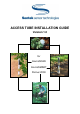
ACCESS TUBE INSTALLATION GUIDE Version 1.
Access Tube Installation Guide EnviroSCAN EnviroSMART Diviner 2000 All rights reserved. No part of this document may be reproduced, transcribed, translated into any language or transmitted in any form electronic or mechanical for any purpose whatsoever without the prior written consent of Sentek Pty Ltd. All intellectual and property rights remain with Sentek Pty Ltd. All information presented is subject to change without notice.
Access Tube Installation Guide Low Res Contents Access Tube Installation Guide i Contents i About this manual 1 Document Conventions 1 Introduction 2 Site Selection 3 What is site selection? 3 Relationship between macro and micro zones in the field 3 Important factors you should know that affect crop water use 4 A general view of macro scale zone selection 7 Micro scale zone selection 10 Micro zone selection guidelines 10 Installing access tubes for Diviner 2000, EnviroSCAN and Envi
Access Tube Installation Guide Low Res About this manual This guide describes the principles of site selection and the materials and methods that are used to install Sentek access tubes. Document Conventions Before you start it is important that you understand the conventions used in this manual.
Introduction Introduction The Access Tube Installation Guide provides important information about how to select monitoring sites and install access tubes. Please read this information prior to installing access tubes. Site selection and access tube installation have a significant impact on the value of the soil moisture data that can be gathered on your property.
Sit e Selection Site Selection The key to effective soil moisture monitoring is to select monitoring sites which truly represent irrigation management areas. The same basic site selection principles apply to the full range of Sentek soil moisture monitoring devices. Many variables influence the spatial distribution of water across an area of land. These variables and their impact on site selection are discussed in more detail below.
Sit e Selection Micro zone selection determines the position of access tubes in relation to the crop and irrigation system. Micro zone selection considers the: • Area of root zone and canopy spread • Water distribution uniformity (sprinkler pattern) • Moisture pattern of drip irrigation • Surface, topographic and soil anomalies The consideration of these factors will assist in finding the best representative position or site for access tube placement within the macro and micro zones.
Sit e Selection Notwithstanding the care taken to delineate macro zones, some variability in soil moisture levels is inevitable. For example: on large properties, rain events may cover only a portion of the land area, replenishing some soil reservoirs and leaving others dry. The aspect or orientation of sloping fields can subject the crop to more or less solar radiation, wind exposure or water run-off – all affecting crop water use.
Sit e Selection Organic Matter The presence of organic matter and humus increases the cation exchange capacity (CEC), water holding capacity and structural stability of soils. Soil che mistry Acid, alkaline, sodic (soils characterized by a dominance of sodium ions) or nutrient deficient conditions impact on expected soil chemical properties. For example: • pH conditions change CEC and the availability of nutrients (by changing their form).
Sit e Selection Cover crop and mulch Cover crops provide more competition for water, but reduce evaporation and facilitate infiltration of rain and irrigation water, reducing run-off. Mulch can improve the infiltration rate of the soil, reduce water run-off, encourage root growth near the soil surface and increase the soil water holding capacity over time, through the accumulation of soil organic matter, and reduce soil temperature.
Sit e Selection The diagrams on the following pages show an example of how ‘factors that affect crop water use’ can be used to determine macro zones. Consult your local soil specialist for further information on the soils at your site.
Sit e Selection From this the requirements for soil improvements and amelioration are outlined: Once the soil has been ameliorated and improved, then the altered soil properties are considered in conjunction with the topography, irrigation system and crop types to delineate irrigation management units.
Sit e Selection Overlaying all this information makes it possible to identify, within a property, areas (zones) that have significantly different requirements. In the example used, the property has been divided into eight macro zones. Each macro zone requires a monitoring site. Potential sites are shown by the dots, but final positioning can be determined by the information in the micro scale zone selection.
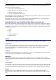
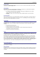
Sit e Selection In the example illustrated below, cans in the blue shaded area received above average water; those in the red shading below average; while those in the green shaded area received an average amount. Due to the specific nature of each site in terms of irrigation system, it is inappropriate to give prescriptive advice on tube placement. For soil moisture monitoring, tube placement should however, be representative and consistent of the area being watered.
Sit e Selection In addition, in drip irrigation, the slope needs to be taken into consideration, to account for movement of water down slope. In furrow irrigated fields, access tubes should be installed 50 to 100 metres away from the head ditch. Access tubes should not be installed solely at the opposite side to the head ditch, as tail water from the irrigation may back up the furrows and give unrepresentative readings.
Installing EnviroSCAN, EnviroSM ART & Diviner 2000 access tubes Installing access tubes for Diviner 2000, EnviroSCAN and EnviroSMART probes Introduction It is necessary to install Sentek access tubes before Sentek sensors can be used to measure volumetric soil water content. Access tubes are installed at selected sites using Sentek installation tools. The tools are specific to the installation method so it is important to understand the installation method before purchasing your installation tools.
Installing EnviroSCAN, EnviroSM ART & Diviner 2000 access tubes Disclaimer: The access tubes, probes and sensors supplied by Sentek are specifically designed to be used together. Other brands of probe and access tube are not compatible with the Sentek products and should not be used as they may damage Sentek equipment through incorrect use and will invalidate warranty agreements. Sentek has developed precision installation tools to be used for the installation of Sentek access tubes.
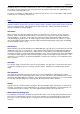
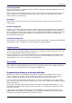
Installing EnviroSCAN, EnviroSM ART & Diviner 2000 access tubes The figure below shows preferential flow of water down the side of the access tube, where the wetting front moves to the bottom sensor almost instantaneously. The movement of wetting front should match the hydraulic properties of the soil, such as shown in the example below.
Installing EnviroSCAN, EnviroSM ART & Diviner 2000 access tubes Standard manual installation method Introduction The Standard manual installation method is recommended for most soil types. In this method the access tube hole is hand augered into the soil, through and slightly ahead of the access tube. This is done using the 47.0 mm Regular Auger. The augered hole is slightly smaller than the access tube.
Installing EnviroSCAN, EnviroSM ART & Diviner 2000 access tubes Toolkit items Item Part Number Standard Access Tube Installation Toolkit Complete 07000 Part A – Auger Kit, includes: 07050 1 x Regular Auger 47.0 mm 70135 1 x Regular (clay) Auger 53.0 mm 70140 2 x Auger Extension Rods (0.5 m) 70125 1 x Auger Extension Rod (1.
Installing EnviroSCAN, EnviroSM ART & Diviner 2000 access tubes 1 x Nylon dolly 70205 1 x Heavy duty dolly 70210 1 x Toolbag No. 3 70300 Miscellaneous items (installer to supply) • A length of rope – to tie branches or vines temporarily out of the way so that they do not get damaged or interfere with the augering process • A set of duck boards – to prevent soil compaction around the access tube during the installation process • 1 x sledge hammer – to drive the access tubes into the soil.
Installing EnviroSCAN, EnviroSM ART & Diviner 2000 access tubes To assemble the tripod at the site: 1. Attach the base plate to the base of the tripod. 2. Centre the access tube installation tripod over the site where the access tube is to be installed. 3. Loosen the wing nuts and spread the legs of the tripod until the base plate touches the ground and the lower legs are protruding approximately 5 cm (2 inches) out of the upper leg sections.
Installing EnviroSCAN, EnviroSM ART & Diviner 2000 access tubes Watch the bubble in the spirit level on the side of the tripod. Move the handle around until the bubble is located in the centre of the level window. 6. When the tripod cylinder is in a vertical position, firmly tighten the wing nuts of the legs. Step 3 – Installing the access tube Access tubes are supplied with 50 cm (20 inches) of extra length to accommodate at least one bottom stopper.
Installing EnviroSCAN, EnviroSM ART & Diviner 2000 access tubes 4. Select the 47.0 mm regular auger head. Note: This auger is designed for all soils and should be used where possible, even in heavy textured soils, as it provides the best possible access tube installation method. The other augers are used to take over when you run into problems. See the Troubleshooting Section for further information. 5. Select the required extension rods and screw the auger head and T-handle to the extension rods.
Installing EnviroSCAN, EnviroSM ART & Diviner 2000 access tubes 7. Disengage the metal “tooth” on the tripod by turning the lever located on the tripod cylinder. The metal “tooth” is designed to prevent the access tube from spinning during augering, and should not be engaged while hammering in the access tube. 8. Insert the access tube with fitted cutting edge into the tripod guide tube, with cutting edge facing downwards. 9. Select the Heavy duty dolly and insert it into the top of the access tube. 10.
Installing EnviroSCAN, EnviroSM ART & Diviner 2000 access tubes depth has been reached. Note: If the access tube spins while augering, engage the metal “tooth” on the tripod by turning the lever located on the tripod cylinder. 12. Use the auger cleaning tool to remove the soil from the auger head. Do not empty the augered soil near the access tube as it may change the infiltration rate of irrigation and rainfall. Dispose of the soil away from the monitoring site. 13.
Installing EnviroSCAN, EnviroSM ART & Diviner 2000 access tubes 16. Auger ahead of the access tube by approximately 10 – 20 cm (4 – 8 inches). Alternate between augering and hammering until the dolly resting on top of the access tube nearly touches the top of the tripod. 17. Insert the yellow Nylon dolly (which has the same diameter as the access tube) into the access tube and continue hammering and augering until the mark on the dolly is level with the top of the tripod.
Installing EnviroSCAN, EnviroSM ART & Diviner 2000 access tubes 20. When all pins are removed, carefully lift the tripod straight upward and off the access tube. 21. Try twisting and moving the tube backwards and forwards while examining the surface soil surrounding the access tube. The tube should not move and there should be no visible air gaps. 22.
Installing EnviroSCAN, EnviroSM ART & Diviner 2000 access tubes Step 4 – Cleaning the access tube The access tube must be cleaned before the top cap is installed and readings are taken. The bottom stopper is installed after cleaning in all soils, except for very wet and saturated soils. In these soils it is installed first to prevent the rise of water into the tube during cleaning. To clean the tube 1. Installing an access tube in most soil types leaves a thin layer of soil coating on the inside wall. 2.
Installing EnviroSCAN, EnviroSM ART & Diviner 2000 access tubes 6. Change cotton cloths as required and continue with the cleaning action until inspection with a flashlight (torch) shows that the access tube is clean and dry. 7. Note: In sandy soils, it may not be necessary to use the nylon brush tool as the access tube can be easily cleaned with the rag tool. An alternative is to use a foam cleaning tool, which is available as an Optional Extra (refer to section on Toolkit Items).
Installing EnviroSCAN, EnviroSM ART & Diviner 2000 access tubes 5. Place the Expandable Bung Tightening Tool over the wing nut and slowly push the bung down the access tube. Allow air to escape until the bung rests on top of the internal cutting edge on the inside of the tube. 6. Slowly turn the T-Handle until you feel you firm resistance to further turning. Note: The bottom stopper bung is designed to run out of thread while tightening.
Installing EnviroSCAN, EnviroSM ART & Diviner 2000 access tubes 2. Take a silicon gun with a new nozzle and apply three rings of silicon around the outside of the access tube, approximately 1 cm (0.4 inch) below the top rim of the tube. 3. Unscrew the cap from the top cap assembly base. 4. For EnviroSCAN and EnviroSMART applications, feed the cable through the FairRite bead and then through the cable gland. 5.
Installing EnviroSCAN, EnviroSM ART & Diviner 2000 access tubes 8. For EnviroSCAN and EnviroSMART probes, strip back the outer sheath of the cable until the end of the outer sheath sits just inside the cable gland. Fill around the wires inside the end of the cable sheath with silicone to prevent moisture from travelling along the cable into the top cap. Insert the electronics and connect the cable to the probe interface.
Installing EnviroSCAN, EnviroSM ART & Diviner 2000 access tubes 5. Insert the assembled auger into the tripod ensuring the centralization poly guide is fitted to the top of the tripod cylinder. 6. Turn the auger 4-5 turns and lift it gently approximately five centimetres, then turn the auger another 3-4 turns. The lifting action moves the soil upward, partially filling the space around the auger head and providing a greater uptake for additional soil.
Installing EnviroSCAN, EnviroSM ART & Diviner 2000 access tubes 3. Fit the Auger Centralization Poly Guide over the extension and attach the T-Handle. 4. Put gloves and safety goggles on to protect your hands and eyes from damage. 5. Insert the assembled auger into the tripod ensuring the centralization poly guide is fitted to the top of the tripod cylinder. 6. Turn the auger 4-5 turns and lift it gently approximately five centimetres, then turn the auger another 3-4 turns.
Installing EnviroSCAN, EnviroSM ART & Diviner 2000 access tubes Gravelly soils If you encounter a layer of small stones or gravel and the 47.0 mm regular auger is unable to proceed, attach the 47.0 mm Open Centre Tungsten Tip Auger. This auger is capable of breaking up and retrieving gravel of up to thumbnail size under most conditions. If you encounter larger stones, attach the 47.0 mm rockbreaker to the reinforced auger extension rod and fit the Heavy Duty T-Handle.
Installing EnviroSCAN, EnviroSM ART & Diviner 2000 access tubes Stony Soils The standard manual installation method is not suitable for stony soils. If you know your soils are very gravely and stony, the Slurry Installation Method must be used (see following pages).
Installing EnviroSCAN, EnviroSM ART & Diviner 2000 access tubes Slurry Installation Method What are the different slurry methods? The slurry installation methods are techniques used in soils with a high stone and gravel content. Stony soils are hard to auger and do not break up evenly. Large air pockets form easily when installing access tubes in these soils, causing unreliable readings.
Installing EnviroSCAN, EnviroSM ART & Diviner 2000 access tubes Note: Slurry installations take some preparation time, and also sufficient time needs to be allowed for the slurry to dry and equilibrate with the surrounding soil before the data can be used. Slurry installations should only be attempted in soils where the standard installation method is not possible.
Installing EnviroSCAN, EnviroSM ART & Diviner 2000 access tubes Additional items for difficult stony soils Item Open Centre Tungsten Tip Auger 61.0 mm Part Number 70045 Rock Breaker 54.0 mm 70025 Auger extension rods re-enforced 1.0 m 70015 Miscellaneous Items (Installer to supply) Length of rope – to tie branches or vines temporarily out of the way so that they do not get damaged or interfere with the augering process.
Installing EnviroSCAN, EnviroSM ART & Diviner 2000 access tubes Installation procedure Step 1 – Glue in bottom stopper The slurry bottom stopper should be glued into the access tube prior to installation. Allow sufficient time for the PVC glue to dry. To prepare the access tube 1. Use PVC cleaning fluid to clean the bottom rim of the slurry bottom stopper and the inside of the access tube. 2. Use PVC glue and apply evenly to both surfaces. 3.
Installing EnviroSCAN, EnviroSM ART & Diviner 2000 access tubes Step 2 – Auger the hole To manually auger the access tube hole 1. Select the required extension rods and screw the regular 61.0 mm (slurry) auger head and T-handle to the extension rods. Note: To add extra extension tubes to an existing auger assembly, place the auger on the ground. Place one foot on either side of the THandle and insert the Tommy bar into the hole of the extension tube below the T-handle.
Installing EnviroSCAN, EnviroSM ART & Diviner 2000 access tubes Hint: If you encounter difficulties augering through rocky or stony soils with the regular 61.0 mm (slurry auger), use the Open Centre Tungsten Tip Auger 61.0 mm or Rock Breaker 54 mm Auger. The Open Centre Tungsten Tip Auger is capable of breaking up and retrieving gravel of up to thumbnail size. The 54 mm rock breaker will allow occasional larger stones to be broken.
Installing EnviroSCAN, EnviroSM ART & Diviner 2000 access tubes Step 3 – Make the slurry Slurry Recipe • 1 part grey cement. • 4 parts kaolinite (potters clay as fine powder). • 5 parts water To mix the slurry on site, either take sufficient quantities of each slurry ingredient and suitable measuring utensils to the site or pre-mix the dry slurry ingredients and store them in a plastic container. 1. Measure out 4 parts kaolinite and 1 part cement and mix in a plastic container. 2.
Installing EnviroSCAN, EnviroSM ART & Diviner 2000 access tubes Step 4 – Insert the access tube To install the access tube in the slurry mixture 1. Insert the sealed access tube into the augered hole. Note: At least 4 cm of extra access tube must protrude from the hole for top cap fitting. 2. If more than 4 cm of tube is protruding and you cannot auger any deeper, mark the point 4 cm above the soil surface on the access tube with a marking pen. 3.
Installing EnviroSCAN, EnviroSM ART & Diviner 2000 access tubes Step 5 – Chip off excess slurry To tidy up around the access tube you may need to do one of the following: • Take a spatula or broad knife and remove the excess dried slurry from the soil surface. A fine white ring around the access tube, bridging the gap between the access tube and soil should be visible.
Installing EnviroSCAN, EnviroSM ART & Diviner 2000 access tubes 6. Screw the cap back onto the top cap housing.
Removing access tubes Removing Access Tubes Access tubes can be removed from a site when the site no longer requires monitoring. The access tubes, top caps and bottom stoppers can be cleaned, stored and reused as required. The access tube extraction tool can be used in conjunction with either the Sentek Extraction Tripod, or with machinery with lifting capacity (e.g. jacks, winches or tractor hydraulics) to remove access tubes.
Removing access tubes 4. Use the Tommy Bars to tighten the T-Handle and Expandable bung tightening tool to the extension rods. 5. Insert this tool into the access tube until you feel the top of the bottom stopper bung. 6. Turn the tool slowly until the slot of the tool slides over the wing nut, which causes the tool to drop 1 cm (0.4 inch) downward.
Removing access tubes 5. Place the hook of the steel cable from the tripod through the upper eye of the extraction tool. Alternatively use a steel cable or strong chain attached to the other lifting device. 6. Winch the access tube carefully upward and out of the ground. 7. Remove the Tube extraction tool from the steel cable or chain, and then remove the tube extraction tool from the access tube. It may be necessary to gently tap on the top of the extraction tool to loosen it. 8.
Toolkit items Toolkit Items Sentek access tube items Part No. 20510 1.0 metre access tube Part No. 21010 1.5 metre access tube Part No. 21510 2.0 metre access tube Part No. 22010 2.5 metre access tube Part No. 80035 Red Cutting edge Part No. 80040 Yellow Cutting edge Part No. 22410 Diviner Top Cap Assembly Part No. 22400 Part No.
Toolkit items Standard Access Tube Installation Kit Complete (Part No. 07000) Part A – Auger Kit (Part Number 07050) Part No. 70100 1 x Tool Bag No 1 The tool bag is a specially designed tool bag that holds and protects all the tools that comprise the auger kit. Part No. 70110 1 x Access Tube Cleaning, Rag Tool The access tube cleaning rag tool holds a cotton cloth threaded through the eyelet. The tool is extended down the access tube.
Toolkit items Part No. 70150 1 x Regular T-handle The T-handle is attached to the auger extension rods, which are attached to the augers to complete the auger assembly. This auger assembly is used to manually drill holes for access tubes. Part No. 70160 1 x Expandable bung tightening tool The expandable bung tightening tool is used to tighten or release the expandable bung, which is inserted in the bottom of the access tube to make the bottom of the access tube watertight. Part No.
Toolkit items Part No. 70215 3 x Tripod anchor pins The 600 mm tripod anchor pins are used to fix the tripod in place during the installation. Part No. 70220 1 x Tripod base plate The base plate is attached to the base of the tripod and prevents the tripod from compacting the soil around the top of the access tube. Part No. 70225 1 x Auger centralization poly guide The auger centralization poly guide is used to centre the auger extension rod within the tripod during predrilling.
Toolkit items Part No. 70030 Heavy Duty T-Handle The Heavy Duty T-Handle is a reinforced T-Handle that attaches to the auger extensions, that is designed to withstand light blows from a sledge hammer. Part No. 70190 Tommy bars The tommy bars are used to tighten and loosen installation tools to and from extension rods. They are also used to combine or detach multiple extension rods. Part No.
Toolkit items Part No. 70180 Access tube cutting tool The access tube cutting tool is a precision PVC pipe cutting tool and is used to cut off any access tube length protruding out of the soil that is not required after the installation process. Part No. 70310 Access Tube Extraction Tripod The access tube extraction tripod has a two-stage winch which is used to remove the access tube from the ground. Part No.
Recommended Reading Recommended Reading Brady, N.C., Weil, R.R., 1996, The Nature and Properties of Soils, 11th Edition, Upper Saddle River, New Jersey, USA, Prentice Hall, Inc. Burt, C.M. 1996, AG-Irrigation Management, Irrigation Training and Research Centre (ITRC), California Polytechnic State University (Cal Poly), San Luis Obispo, California, USA. Hillel, D., 1998, Environmental Soil Physics, Academic Press, San Diego, California, USA. Merriam, J.L., Keller, J.