
User Manual


APPENDIX A. CR10 *9 MODE - STORAGE MODULE COMMANDS
A-2
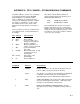
COMMAND DISPLAY
DESCRIPTION
5 DISPLAY STATUS (A to advance to each window)
01:ABCD Window 1:
AB SRP location (chip no.)
CD Total good RAM chips (1-22)
02:ABCD Window 2:
AB DLP location (chip no.)
C Unloaded Batt. Chk. 0=low, 1=OK
D No. of Programs stored (Max=8)
03:A0CD Window 3:
A Errors logged (up to 9)
0 Not Used
C Memory Config. (0=ring, 1=fill & stop)
D Memory Status (0=not full, 1=full)
04:X.XXXX PROM signature (0 if bad PROM)
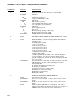
6 06:0X BATTERY CHECK UNDER 100 OHM LOAD (0=low, 1=OK)
7 07:00 DISPLAY DATA - select the Storage Module Area with the
following codes:
0 Dump pointer to SRP
1 File 1, current file
2 File 2, previous to file 1
3 File 3, previous to file 2
4 File 4, previous to file 3
5 File 5, previous to file 4
7 Display location pointer to SRP
9 Oldest data to SRP
1-5 will loop within file boundaries, 0, 7, 9 allows display to
cross boundaries. If no file is found, the display returns
"07:00". At this point, another file can be entered by entering
the correct code.
07:XXXXXX Key A to advance to first data. If another location is keyed in,
SM will jump to 1st start of array following that location.
Review data with:
A Advance and display next data point
B Backup one data point
# Display location, C to return to data
#A Advance to next start of Array
#B Backup to start of Array
#D Return to 9X:00
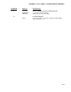
8 DUMP TO ANOTHER STORAGE MODULE
08:00 Select Area as in 7 above
01:XXXXXX First Loc. in area selected. To alter, enter location of start
dump.
02:XXXXXX Final Loc. in area selected. To alter, enter location of end
dump.
03:XX Enter destination SM address (1 through 8). The end-of-
dump location will be shown when the transfer is complete. If
000000 returns, there was an error in transmission.