
Operating System Addendum for CR510, CR10X, and CR23X Owner's manual
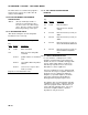
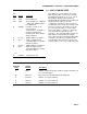

Table Of Contents
- Revision and Copyright Information
- TD and PakBus Operating System Addendum for CR510, CR10X, and CR23X Manuals
- MEASUREMENT AND CONTROL MODULE OVERVIEW
- SECTION 1. FUNCTIONAL MODES
- 1.5 MEMORY ALLOCATION - ?A
- MEMORY TESTING AND SYSTEM STATUS - ?B
- 1.7 *C MODE -- SECURITY
- 1.8 *D MODE – TRANSFER PROGRAMS, GENERAL SETTING
- 1.8.1 ERASING CURRENT PROGRAM
- 1.8.2 PROGRAM TRANSFER WITH STORAGE MODULE
- 1.8.3 FULL/HALF DUPLEX
- 1.8.4 SET DATALOGGER ID
- 1.8.5 SETTING POWERUP OPTIONS
- 1.8.6 SET INITIAL BAUD
- 1.8.7 SET PROGRAM COMPILE OPTION
- 1.8.8 SET PAKBUS ADDRESS
- 1.8.9 ALLOCATE MEMORY FOR GENERAL PURPOSE FILES
- 1.8.10 VIEW ROUTING TABLE
- 1.8.11 SET PAKBUS ROUTER BEACON INTERVAL
- 1.8.12 PAKBUS NEIGHBOR FILTER
- 1.9 *9 DATA TABLES SIZES.
- SECTION 2. INTERNAL DATA STORAGE
- SECTION 3. INSTRUCTION SET BASICS
- SECTION 8. PROCESSING AND PROGRAM CONTROL EXAMPLES
- 8.1 COMPUTATION OF RUNNING AVERAGE
- 8.2 RAINFALL INTENSITY
- 8.3 USING CONTROL PORTS AND LOOP TO RUN AM416 MULTIPLEXER
- 8.4 INTERRUPT SUBROUTINE USED TO COUNT SWITCH CLOSURES (RAIN GAGE)
- 8.5 SDM-A04 ANALOG OUTPUT MULTIPLEXER TO STRIP CHART
- 8.6 CONVERTING 0-360 WIND DIRECTION OUTPUT TO 0-540 FOR STRIP CHART
- 8.7 LOGARITHMIC SAMPLING USING LOOPS
- SECTION 9. INPUT/OUTPUT INSTRUCTIONS
- SECTION 11. OUTPUT PROCESSING INSTRUCTIONS
- SECTION 12. PROGRAM CONTROL INSTRUCTIONS
- Wireless Networks
- PakBus Get/Send Locations (P190)
- Send Final Storage Data (P191)
- Send Message (P192)
- Wireless Network Master (P193)
- Seconds Until Transmit (P194)
- Use Remote Clock Report (P195)
- Wireless Network Remote (P196)
- Force Route (P197)
- Set Setting (P198)
- Routing Table Information (P199)
- PakBus Settings (Options | PakBus Settings)

TD ADDENDUM SECTION 1. FUNCTIONAL MODES
AD-1-5
1.8.6 SET INITIAL BAUD
Table 1.8-10 shows the option codes available
for
setting the initial baud rate. Setting the initial
baud rate forces the CR10X to try the selected
baud rate first when connecting with a device.
TABLE 1.8-9. Set Initial Baud Rate / Set
RS232 Power
Key
Entry Display Comments
*D 13:00 Enter Command
12A 12:00 Connect Baud Rate
Enter Baud Rate Code X
(Table 1.8-11).
TABLE 1.8-10. Baud Rate Codes
X = 0 300 Baud
X = 1 1200 Baud
X = 2 9600 Baud
X = 3 76.8 K Baud
1.8.7 SET PROGRAM COMPILE OPTION
Command 13 is not supported in Table Data
operating s
ystems.
1.8.8 SET PAKBUS ADDRESS
*D 15 allows the user to set the PakBus
Addr
es
s of the datalogger and to set the
maximum size for its routing table.
TABLE 1.8-11. PakBus Address and
Routing Table
Key
Entry Display Comments
*D 13:00 Enter Command
15A 15:xxxx PakBus Address , Enter zero if
the datalogger is
not to be used
as a PakBus device (1..4094 is
legal, the default is 1)
A 01:xxxx If the datal
ogger i
s to be used a
a router, enter the maximum
number of nodes (PakBus
Addresses) to allocate space
for in the pakbus network. 0 =
leafnode, <>0 = router
A 02:xxxx Enter the maximum number of
neighbor
s
in the pakbus
network to allocate space for.
This parameter is used only if
datalogger is used as a router
(01: is non-zero).
A 03:xxxx Enter maximum number of
r
outer
s in the pakbus network
to allocate space for. This
parameter is used only if
datalogger is used as a router
(01: is non-zero).
A 04:xxxx Enter the PakBus address for a
def
ault r
outer (1..4094, 0 for no
default router). The default
router is used for a message if
the destination PakBus
address is not in the routing
table. A router discovering new
routes will not explore beyond
its own default router.
The memory for a routing table comes out of
the pool for program, input locations, and
intermediate storage.
The total number of bytes used for the routing
table =
Nodes x 12
+ Neighbors x 8
+ Routers x 6
+ (Routers x (Nodes – Routers) + (Routers
x
(
Routers – 1))/2) x 4