
Operating System Addendum for CR510, CR10X, and CR23X Owner's manual
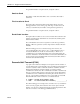


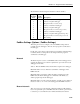
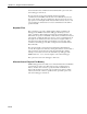
Table Of Contents
- Revision and Copyright Information
- TD and PakBus Operating System Addendum for CR510, CR10X, and CR23X Manuals
- MEASUREMENT AND CONTROL MODULE OVERVIEW
- SECTION 1. FUNCTIONAL MODES
- 1.5 MEMORY ALLOCATION - ?A
- MEMORY TESTING AND SYSTEM STATUS - ?B
- 1.7 *C MODE -- SECURITY
- 1.8 *D MODE – TRANSFER PROGRAMS, GENERAL SETTING
- 1.8.1 ERASING CURRENT PROGRAM
- 1.8.2 PROGRAM TRANSFER WITH STORAGE MODULE
- 1.8.3 FULL/HALF DUPLEX
- 1.8.4 SET DATALOGGER ID
- 1.8.5 SETTING POWERUP OPTIONS
- 1.8.6 SET INITIAL BAUD
- 1.8.7 SET PROGRAM COMPILE OPTION
- 1.8.8 SET PAKBUS ADDRESS
- 1.8.9 ALLOCATE MEMORY FOR GENERAL PURPOSE FILES
- 1.8.10 VIEW ROUTING TABLE
- 1.8.11 SET PAKBUS ROUTER BEACON INTERVAL
- 1.8.12 PAKBUS NEIGHBOR FILTER
- 1.9 *9 DATA TABLES SIZES.
- SECTION 2. INTERNAL DATA STORAGE
- SECTION 3. INSTRUCTION SET BASICS
- SECTION 8. PROCESSING AND PROGRAM CONTROL EXAMPLES
- 8.1 COMPUTATION OF RUNNING AVERAGE
- 8.2 RAINFALL INTENSITY
- 8.3 USING CONTROL PORTS AND LOOP TO RUN AM416 MULTIPLEXER
- 8.4 INTERRUPT SUBROUTINE USED TO COUNT SWITCH CLOSURES (RAIN GAGE)
- 8.5 SDM-A04 ANALOG OUTPUT MULTIPLEXER TO STRIP CHART
- 8.6 CONVERTING 0-360 WIND DIRECTION OUTPUT TO 0-540 FOR STRIP CHART
- 8.7 LOGARITHMIC SAMPLING USING LOOPS
- SECTION 9. INPUT/OUTPUT INSTRUCTIONS
- SECTION 11. OUTPUT PROCESSING INSTRUCTIONS
- SECTION 12. PROGRAM CONTROL INSTRUCTIONS
- Wireless Networks
- PakBus Get/Send Locations (P190)
- Send Final Storage Data (P191)
- Send Message (P192)
- Wireless Network Master (P193)
- Seconds Until Transmit (P194)
- Use Remote Clock Report (P195)
- Wireless Network Remote (P196)
- Force Route (P197)
- Set Setting (P198)
- Routing Table Information (P199)
- PakBus Settings (Options | PakBus Settings)

Section 12. Program Control Instructions
12-17
The information returned using this instruction would be similar to:
Input
Loc
ation
Used
Value
Stored Description
1 3 Address of destination datalogger
2 3 Address of repeater datalogger
3 1 Response metric, 1 second (1 hop)
4 4 Address of destination datalogger
5 3 Address of repeater datalogger
6 2 Response metric, 2 seconds (2 hops, 3 & 4)
7 5 Address of destination datalogger
8 3 Address of repeater datalogger (first hop only)
9 3 Response metric, 3 seconds (3 hops, 3, 4 & 5)
10 -1 End of string
PakBus Settings (Options | PakBus Settings)
This dialog box is used to configure some of the PakBus settings, that are
normally set in the datalogger's *D mode, when a program is downloaded to
the datalogger.
For all of the options below, if the check box Do Not Change Current Settings
is enab
led, then those settings will not be changed when the program is
downloaded to the datalogger.
Network
The Network option is used to set the PakBus address in the datalogger and to
configure the datalogger as a router if required. This option is the same as the
datalogger's *D19 mode.
Address - Enter the PakBus address that should be assigned to the datalogger.
Maximum number of nodes - Enter the total number of dataloggers in the
P
a
kBus network.
Maximum number of neighbors - Enter the number of dataloggers in the
Pa
kBus network that the datalogger can communicate with directly (i.e.,
without going through another datalogger).
Maximum number of routers - Enter the number of neighbors to the datalogger
that act as
routers to one or more other dataloggers in the PakBus network.
Beacon Intervals
This option is used to set the interval on which the datalogger will transmit a
beacon out a particular port to the PakBus network. Use the drop-down list box
to select the port over which the beacon will be transmitted, and enter the