TDR Probes CS605, CS610, CS630, CS635, CS640, CS645 Revision: 9/13 C o p y r i g h t © 2 0 0 6 - 2 0 1 3 C a m p b e l l S c i e n t i f i c , I n c .
Warranty “PRODUCTS MANUFACTURED BY CAMPBELL SCIENTIFIC, INC. are warranted by Campbell Scientific, Inc. (“Campbell”) to be free from defects in materials and workmanship under normal use and service for twelve (12) months from date of shipment unless otherwise specified in the corresponding Campbell pricelist or product manual. Products not manufactured, but that are re-sold by Campbell, are warranted only to the limits extended by the original manufacturer.
Assistance Products may not be returned without prior authorization. The following contact information is for US and international customers residing in countries served by Campbell Scientific, Inc. directly. Affiliate companies handle repairs for customers within their territories. Please visit www.campbellsci.com to determine which Campbell Scientific company serves your country. To obtain a Returned Materials Authorization (RMA), contact CAMPBELL SCIENTIFIC, INC., phone (435) 227-9000.
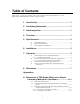
Table of Contents PDF viewers: These page numbers refer to the printed version of this document. Use the PDF reader bookmarks tab for links to specific sections. 1. Introduction .................................................................1 2. Cautionary Statements...............................................1 3. Initial Inspection .........................................................1 4. Overview......................................................................1 5. Specifications ...........
Table of Contents B. Correcting Electrical Conductivity Measurements for System Losses......................B-1 B.1 B.2 Description of Method..................................................................... B-1 Detailed Method Description........................................................... B-2 B.2.1 Collecting Reflection Coefficient with Probes Open and Shorted.................................................................................. B-2 B.2.2 Determining Kp ............................
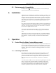
TDR Probes CS605, CS610, CS630, CS635, CS640, CS645 1. Introduction This document presents descriptions and instructions for Campbell Scientific Time Domain Reflectometry (TDR) probes and includes some TDR principles. Consult the TDR100 operating manual for comprehensive TDR instructions. A single TDR probe can be connected directly to the TDR100 or multiple probes connected via the SDMX50-series Coaxial Multiplexers. Before using the TDR probes, please study: • • 2. 3. 4.
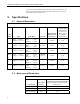
TDR Probes CS605, CS610, CS630, CS635, CS640, CS645 as a change in probe impedance which affects the shape of the reflection. The shape of the reflection contains information used to determine water content and soil bulk electrical conductivity. 5. Specifications 5.1 Physical Description TABLE 5-1. TDR Probe Physical Properties Probe Model Rods Probe Head Cable Type CS605 length 30.0 cm diameter 0.475 cm length width thickness 10.8 cm 7.0 cm 1.9 cm RG58 CS610 length 30.0 cm diameter 0.
TDR Probes CS605, CS610, CS630, CS635, CS640, CS645 5.3 Electromagnetic Compatibility All TDR probes are compliant with performance criteria available upon request. RF emissions are below EN55022 limit. 6. Installation TDR probes can be installed in any orientation: horizontally, vertically, or at an angle to the surface. The measured water content is the integral or average of the water content over the length of the probe rods.
TDR Probes CS605, CS610, CS630, CS635, CS640, CS645 Calculation, with all cabling from TDR100 to probe in place will compensate for the cable losses. Probe offset values obtained this way will be greater than those listed in TABLE 5-2. 7.2 Probe Constant for Electrical Conductivity Measurement The electrical conductivity measurement requires a probe constant to account for probe geometry. The probe constant is commonly referred as Kp.
TDR Probes CS605, CS610, CS630, CS635, CS640, CS645 datalogger algorithm to analyze the waveform are shifted by the cable losses resulting in error. For the data shown in FIGURE 7-1, the water content measurement using the 66 meter cable was in error by about 1.5% volumetric water content when electrical conductivity is low. However, in saline soils, the error can be several percent. See Bilskie (1997) for complete results of the study.
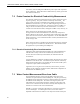
TDR Probes CS605, CS610, CS630, CS635, CS640, CS645 can affect the accuracy and resolution of water content measurements. FIGURE 7-2 presents a series of waveforms when a solution with an electrical conductivity of 1.0 dS m-1 is added to a soil which has essentially no salt present. FIGURE 7-3 shows data for solution with high electrical conductivity. water content = 9.5% water content = 25% FIGURE 7-2. Waveforms collected in a sandy loam using CS610 probe with RG8 connecting cable.
TDR Probes CS605, CS610, CS630, CS635, CS640, CS645 The combined effect of long cable runs and high soil electrical conductivity must be considered when TDR measurements are taken. 8. References Bilskie, Jim. 1997. “Reducing Measurement Errors of Selected Soil Water Sensors.” Proceedings of the International Workshop on Characterization and measurement of the hydraulic properties of unsaturated porous media. 387396. Castiglione, P. and P.J. Shouse. 2003.
TDR Probes CS605, CS610, CS630, CS635, CS640, CS645 8
Appendix A. Discussion of TDR Probe Offset and a Simple Laboratory Method for Calculation A.1 Discussion of Probe Offset Probe offset accounts for the segment of the TDR probe rods that is part of the probe head and is not exposed to the media surrounding the probe rods. The location of the beginning of the probe that is calculated in the TDR100 operating system is the point along the cable where the transition from the 50 ohm cable to the TDR probe impedance occurs.
Appendix A. Discussion of TDR Probe Offset and a Simple Laboratory Method for Calculation A.2 The Compounding Effect of Signal Attenuation in Connecting Cables The probe offset values provided in the operating manual were calculated from measurements in the Campbell Scientific soils laboratory. The method is described below. The length of cable for the laboratory calculations was 3 meters or less. As cable length increases, signal loss occurs in both amplitude and bandwidth.
Appendix A. Discussion of TDR Probe Offset and a Simple Laboratory Method for Calculation A.3 Method for Calculating Probe Offset Using Information from the Terminal Mode of PC-TDR Letting Vp = 1 and solving [1] for ProbeOffset gives: ProbeOff = end − start − La [A3] The start and end distance values are determined by an algorithm in the TDR100 operating system.
Appendix A. Discussion of TDR Probe Offset and a Simple Laboratory Method for Calculation 4. Enter Terminal Mode using Options/Terminal Emulator. 5. Press Enter until > appears 6. Type GVAR then Enter. 7. It is recommended that step 6 be repeated several times and that the average values of Start and End be used for following calculations. (the line commands are not case sensitive) GVAR returns the uncorrected Start and End. These values must be converted to distance from index values.
Appendix A. Discussion of TDR Probe Offset and a Simple Laboratory Method for Calculation end distance := end index • WindowLength datapoints − 1 start distance = 0.65 Pr obeOffset := end distance = 3.4 ( − La • Vp − end distance + start distance ) Vp ProbeOffset = 0.086 TABLE A-1. Dielectric permittivity values for range of temperatures. From equation [A5]. Temperature (°C) Dielectric Permittivity 15 82.23 15.5 82.04 16 81.85 16.5 81.67 17 81.48 17.5 81.29 18 81.1 18.5 80.
Appendix A. Discussion of TDR Probe Offset and a Simple Laboratory Method for Calculation TABLE A-1. Dielectric permittivity values for range of temperatures. From equation [A5]. A-6 Temperature (°C) Dielectric Permittivity 27 77.82 27.5 77.65 28 77.47 28.5 77.29 29 77.12 29.5 76.94 30 76.
Appendix B. Correcting Electrical Conductivity Measurements for System Losses TDR system cabling and multiplexers introduce losses of the applied and reflected signals which can lead to error in measurement of electrical conductivity. The following information is based on a method presented in paper published by Castiglione and Shouse (2003). The method has been tested by Campbell Scientific and found to provide excellent results.
Appendix B. Correcting Electrical Conductivity Measurements for System Losses electrical conductivity. Kp is calculated as the ratio of electrical conductivity to electrical conductance and presented in equation [B3]. Kp = σ G [B3] With Kp determined, a calibration equation can be derived that corrects EC measurements for system losses. B.2 Detailed Method Description B.2.
Appendix B. Correcting Electrical Conductivity Measurements for System Losses The temperature effect is described by: EC T = EC 25 • (1 + 0.02 • (T − 25)) [B4] where EC 25 is the electrical conductivity at 25ºC and EC T is the electrical conductivity at other temperatures. B.2.3 Deriving Calibration Function Using the Kp, ρopen and ρshorted values for each probe, the uncorrected electrical conductivity as measured by the TDR100 can be corrected to give accurate EC values that account for system losses.
Appendix B. Correcting Electrical Conductivity Measurements for System Losses B.2.4 CR1000 Program for Collecting ρopen and ρshorted Values 'This example program is written for 4 TDR probes connected to 'a single multiplexer. It will be necessary to add instructions in 'subroutine TDR if more probes are used.
Appendix B.
Appendix B.
Campbell Scientific Companies Campbell Scientific, Inc. (CSI) 815 West 1800 North Logan, Utah 84321 UNITED STATES www.campbellsci.com • info@campbellsci.com Campbell Scientific Africa Pty. Ltd. (CSAf) PO Box 2450 Somerset West 7129 SOUTH AFRICA www.csafrica.co.za • cleroux@csafrica.co.za Campbell Scientific Australia Pty. Ltd. (CSA) PO Box 8108 Garbutt Post Shop QLD 4814 AUSTRALIA www.campbellsci.com.au • info@campbellsci.com.au Campbell Scientific do Brasil Ltda. (CSB) Rua Apinagés, nbr.