21X MICROLOGGER OPERATOR'S MANUAL REVISION: 8/95 CopynlcHT (c) 1994, 1995 CAMPBELL sclENTlFlc, lNc.
WARRANTY AND ASSISTANCE The 21X MICROI-OGGER is warranted by CAMPBELL SCIENTIFIC, lNC. to be free from defects in materials and wofkmanship under normal use and seruice for thifty-six (36) months from date of shipment unless specified {thenrvise. Batteries have no warranty. CAMPBELL SCIENTIFIC, lNC.'s obligation under this warranty is liririted to repairing or replacing (at CAMPBELL SCIENTIFIC, lNC.'s option) defective products.
21X OPERATOR'S MANUAL TABLE OF CONTENTS PAGE WARRANW AND ASSISTANCE DETA1LS............ CAUTIONARY NOTES............. SELECTED OPERATING .......'................ v ...'..... vl OVERVIEW OV1. PHYSICAL DESCRIPTION OV1.1 Arlalog Inputs OV1.2 Switched Excitation Outputs...... OV1.3 Continuous Analog Outputs OV1.4 Dibital Control Ports .......... OV1.5 PUIse Count lnputs OV1.6 14 Volts and Ground ov2. .'..OV-2 ........'.'... OV-3 ' OV-3 '.. OV-3 ..'.'..........OV-3 ..."......
TABLE OF CONTENTS PROGRAMMING 1. 1.1 1.2 1.3 1.4 1.5 1.6 1.7 1.8 2. 2.1 2.2 2.3 3. 3.1 3.2 3.3 3.4 3.5 3.6 3.7 3.8 3.9 3.10 FUNCTIONAL MODES Setting and Displaying the Clock - *5 Mode Displaying and Altering Input.Mernory or Flags Compiling and Logging Data - *0 Memory Allocation Memory Testing and System Status - *B C Mode *D Mode - Save or Load Program Mode *A............. Mode Security.... 4.1 4.2 4.3 4.4 4.5 5.
TABLE OF CONTENTS PROGRAMMING EXAMPLES PAGE REMENT PROGRAMMING EXAMPLES 7. Pyranometer................. Supply Reference.............. 7.2 7.3 7.4 7.5 7.6 7.7 Probe Probe... Output Leads Bridge. Bridge. .........i......... Bridge.. Bridge.. Bridge.. Block 101)............ Rejection.... ..........7-3 .............
TABLE OF CONTENTS INSTALLATION 14. INSTALLATION AND MAINTENANCE 14.1 14.2 14.3 '14.4 14.5 14.6 14.7 14.8 14.9 14.10 Pane1s................. 21X............ Connections Solar Direct Battery Connection to the Vehicle Power Supply Use of DigitalControl Ports for Switching Relays...,.... Grounding.. Maintenance................. Calibration ......... 1 .............. 1 .......... 1 ................... 14 .........14 .........14 Procedures. ......... 1 APPENDICES A. GLOSSARY................ B.
I I I I I I I l I i SELECTED OPERATING DETAILS I I 1. I StorinolData - Data is stored in Final Storag-{ only by Output Processing Instruiiions and only when the Output Flag is set. i(Sections OV2 and OV3.3) 2. Storing Date and Trme Date and time are stored in Final Storage ONLY if the Reat Time lrlrstruclionTT is used. (Section 11) 3. Data Tians{er - On-line data transfer f Final Qtorage to peripherals (tape, printer, Storagp Mo.-dule,'etc.
CAUTIONARY NOTES ? Damage will occur to the analog input circuitry if voltages in excess of r16 V are applied for a sustained period. Voltages in excess of t8V will cause errors and possible overranging on other analog input channels. 2. There are frequent references in this manualto Storage Modules. The Storage Modules referred to are the SM192 and SM716. The old SM16 and SM64 Storage Modules cannot pedorm many of the functions available with the SM192 and sM716.
21 X MICROLOGGER OVERVIEW The 21X Mi ologger combines precision measurement with processing and control capability in a single battery oper ted system. Campbell SQientific, lnc. provides three documents to aid in understanding and operating the 21X: 1. 2. 1 3. I This Overuiew The 21X Operator's Manual fne 21X Prompt Sheet i This Overui$w introduces the concepts required to take advantage of the 21X's capabilities. Hands-on programmin! examples start in Section OV4.
21 X MICROLOGGER OVERVIEW The 9-pin serial l/O port provides connection to data storage peripherals, such as the SM192t16 Storage Module or RC35 Cassette Recorder, and provides serial communication to computer or modem devices for data transfer or remote programming (Section 6). This 9 pin port does NOT have the same pin configuration as the 9 pin serial ports currently used on many personalcomputers. An SC32A is required to ANAIOG INPIIIS Input/Output Instructions 1. Volt (SE) 2. vott (uFF) 4.
. ovl.2 EXCITATION OUTPUTS The first fou numbered terminals on the lower are the SWITCHED EXCITATION terminal channels. supply programmable for resistive bridge excitation ts. The excitation channels are on during the rneasurement. only ovl.3 ANALOG OUTPUTS The two Codtinuous Analog Output (CAO) channels suSply continuous output voltages, under program control, for use with strip charts, X-Y plotters, or proportional controllers. OV1.4 DIGITAI..
21X MICROLOGGER OVERVIEW INPUT/OUTPUT Sensor Control INSTRUCTIONS Specify the conversion of a sensor signal to a data value and store it in Input Storage.
21X MICROLOGGER OVER\NEW 3. Final used to develop high level algorithms to process measurements prior to Output Processing (Section 1 0). ge - Final, processed values are for transfer to printer, tape, solid Module or for retrieval via links. Values are stored in Final only by the Output Instructions and only when the is set in the users program. The Output allocated' to Final Storage at 19,296 power is reduced if Input or Intermediate is increased.
21X MICROLOGGER OVERVIEW Table 1. Execute every x sec. 0.0125
21X MICROLOGGER OVERVIEW 21X. Work examples in and you will wellas an the for loading the direct programming overuiew before using EDLOG the basics ol21X operation as ion for the help provided by Section OV3.5 describes options program into the 21X. OV3.1 FUNCTIONAL MODES User interaction with the 21X is broken into different fun$tional MODES, (e.9., programming the measurdments and output, setting time, manually ini{iating a block data transfer to etc.).
21 X MICROLOGGER OVERVIEW OV3.4 INSTRUCTION FORMAT Instructions are identified by an instruction number. Each instruction has a number of parameters that give the 21X the information it needs to execute the instruction. The 21X Prompt Sheet has the instruction numbers in red, with the parameters briefly listed in columns following the description. Some parameters are footnoted with further description under the "lnstruction Option Codes" heading.
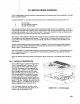
21X MICROLOGGER OVERVIEW OV4.1 SAMPLE PROGRAM 1 I The 21X ha$ a thermistor built into the input panelthat nieasures the paneltemperature and provides a rlference for thermocouple temperaturel measurements. In this example the 21X is programmed to read the panel temperature every 5 seconds and send the results directly to Final Storage. TURN ON THE POWER SWITCH AND PROCEED AS INDICATED Display Shows Key (lD:Data) Explanation HELLO On power-up, the 21X displays "hello" while it checks the memory.
21 X MICROLOGGER OVERVIEW Display Shows Key (lD:Data) Explanation "0 :LOG Exit Table 1, enter *0 mode to compile table and begin measurements. "6 06:0000 Enter *6 mode to view Input Storage. A 01:21.234 Advance to Input Storage location 1. Panel temperature is 21 .234oC. 1 Wait a few seconds: O1:21.423 The measurement will be updated every 5 seconds when a new measurement is made. At this point the 21X is measuring the temperature every 5 seconds and sending the value to Input Storage.
21X MICROLOGGER OVERVIEW Display Shows Key A (lD:Data) 02:0000 1 O2:1 Explanation Enter repetition and advance to the second parameter which specifies the first lnput Storage location to sample. lnput Storage location 1, where the panel temperature is stored. i ] ] I ] A 04:P00 *0 :LOG 1 Enter location and advance to fourth instruction location. Note that a value is not entered into memory untilA is keyed.
21X MICROLOGGER OVERVIEW will be insefted at that point in the table, advance through and enter the parameters. The Instruction that was at that point and al instructions following it will be pushed down to follow the inserted instruction. An instruction is deleted by advancing to the instruction number (P in display) and keying #D (Table OV3-2). value then key A. Note that the new value is entered untilA is keyed.
X MICROLOGGER OVERVIEW Parameter 3 ]specif ies the channel on which to make the firdt measurement. Parameter 6 specifies thellnput Storage location in which to store the firsf channel measurement. lf multiple repetitions afe specified, measurements from sequentialc$annels are stored in adjacent input locations beginning with the location specified in Parameter 6. For Example, if there are 5 oC when a multiplier of 1 and an offset of 0 are used. The first example was explained one keystroke at a time.
21X MICROLOGGER OVERVIEW Instruction (Loc.:Entry) Parameter (Par.#:Entry) O4:P77 01:10 05:P71 01:1 O2:2 To obtain daily output, the lf Time instruction is again used to set the Output Flag and is followed by the Output lnstructions to store time and the daily maximum and minimum temperatures and the time each occurs. Any Program Control lnstruction which is used to set the Output Flag high will set it low if the Description Output Time Slore hour and minute. Average One repetition.
2fX MICROLOGGER OVERVIEW' Display Shows Key (lD:Data) Explanation "5 00:21:32 Enter *5 mode. Clock running but not set correctly. A 05:89 Advance to YEAR location. 90 05:90 Key in current year (1990). A 05:0076 Enter and advance to day of year. 197 05:197 Key in day of year. The 21X Prompt Sheet has a day of year calendar. A 05:00:21 Enter and advance to hour and minute. 1324 05:1324 Key in hrs:min (1:24 PM in this example). A ;13;24:01 Clock set and running.
21X MICROLOGGER OVERVIEW and exchanged for the one which is retrieved so that data collection can continue uninterrupted. 2. Bring a storage device to the datalogger and transfer all the data that has accumulated in Final Storage since the last visit. 3. Retrieve the data over some form of telecommunications link, that is, Radio Frequency (RF), telephone, shod haul modem, multi-drop interface, or satellite. The PC208 TELCOM program automates this process for IBM PCIXTIATIPS-2's and compatibles.
21X MICROLOGGER OVERVIEW DATA RETRIEVAL DATALOGGER G €'g !o 9c OO gf -oF ge I H U b te I Jf trJ O- P5{) U EE I "3 !!t o IRANSCEI\ER Eo I W,/ANTENNA & CABLE H; o I RAOIO EE o H t/,I E 5 G = o ct P50 P H an RADIO IRANSCEIVER G 3 VANTENNA & CAALE "":6'_.i coMPUTER ASn{CflRONOUS SERIAL N = U 6 E L lla aaa aaa taa RS-232 . CABLE coMuuNtcAlloNs I u z I -J--...--...--J PORT NoE+ 1. 2. AODITIONAL METHOOS OF DATA REIREIVAL ARE A. SATELUIE IRANSMISEON B.
21X MICROLOGGER OVERVIEW OV6. SPECIFICATIONS The folloriqg elecrical 3p€ctfica*mt .rc vald NUMBER OF CHANNELS: I ditterenria, o. up to 16 singl$ended. Eacfi dilleren0al channol can bo configured ar two 3ingllend€d chsnnel3. CHANNEL EXPANSION: The f&del Al,L16 Relav Multigleret allows atl edditionet 64 sineb-end€d channels to multipler into lour 21X singllended channels. Up to tout Alt 416'3 cNn be @.rn€ctod to ona 2l X.
SECTION 1. FUNCTIONAL TABLES -*1,*2, AND *3 1.1 MODES When a display and 00 in will an existing instruction 21X will 5 will table). 1.1.1 The seconds as 0.0125.... measurement) is 256 measurements per second (16 measurements repeated 16 times per second). and processing functions are Data acqu controlled b]l instructions contained in program can be separated into 2 tables. tables, each having its own programmable execution inlerval.
SECTION 1. FUNCTIONAL MODES 1.1.3 TABLE PRIORITY/INTERRUPTS Table 1 execution has priority over Table 2. lf Table 2 is being executed when it is time to execute Table 1, Table 2 will be interrupted. After Table 1 is completed, Table 2 resumes at the point of interruption. lf the execution interval of Table 2 coincides with Table 1, Table 1 will be executed first, followed by Table 2.
SECTION 1. FUNCTIONAL MODES' *1 *2, *3, or *4 output ff any program tables , options are altered and complied in the.0 Mode, values in Input Storage will be set to 0. To preserue values entered in Input Siorage, A Advance to next location or enter B -up to previous location C Key C, then value, then A) D # current location and allow a tion no. to be keyed in, followed A to jump to that location 1.3.1 DISPLAYING AND ALTERING INPUT STORAGE When *6 is fieyed, the display will read "06:0000".
SECTION 1. FUNCTIONAL MODES compilation. The display is not updated after entering *0. When the *0, *B, or *D Mode is used to compile, all output ports and flags are set low, the timer (lnstruction 26) is reset, and data values contained in Input and Intermediate Storage are RESET TO ZERO. The 21X should normally be left in the.0 Mode when logging data. This Mode requires slightly less power than Modes which frequently update the display. 1.5 MEMORY ALLOCATION . -A 1.5.
SECTION 1.5.2 *A MODE is used to 1) determine the allocated to Input, number of Intermediatel and Final Storage; 2) repartition this 3) check the number of bytes memory; 4) erase Final remaining in Storage; an{ 5) to completely reset the *A is keyed, the first value datalogger. displayed is {he number of memory locations allocated to lhput Storage. Press A to advance through the fiemory values. Table 1.
SECTION 1. FUNCTIONAL MODES 1.6 MEMORY TESTING AND SYSTEM Third PROM Signature STATUS. -B 05: XXXXX The.B Mode is used to 1) read the signature of the program memory and the software PROMs, 2) display the power-up memory status, 3) display the number of E08 occurrences (Section 3:10), 4) display the number of overrun Memory status, decimal equivalent to the 1s and shown on power-up (Section 1.5.1 e.9., 11111111=255) 06: XXXXX No. of E08 occurrences (Key in 88 to reset) 07: XXXXX No.
SECTION TABLE 1. 1. *G Mode Entries and Codes Key Entry Description *c Enter current password. lf correct, then advance, else exit *C Mode. 12:00 indicates *C Mode is not in PROMS. lf security is disabled, *C advances directly to window 1. 12:0000 A Window 1, enter command: 01:0p 00 01 0Z:{ XXX A = = disable security and advance to window *0 or 2; subsequent *6 enables security. s€curity remains enabled, but it advances to window 2 and allows entry of a new password.
SECTION 1. FUNCTIONAL MODES 1.8.1 TRANSFER TO COMPUTER/PRINTER 5:P0 This section describes commands 1 and 2 (Table 1.8-1). TERM (PC208 Software) automaticaily uses these commands for uploading and downloading programs. MODE 2 SCAN RATE MODE 3 SENDING ASCII PROGRAM INFORMATION MODE 4 Command 1 is to send the program listing in ASC|l. At the end of the listing, the 21X sends control E (5 hex or decimal) twice. Except when in telecommunications, the baud rate code must be entered after command 1.
,SECTION 4.A n (;) tells the 21X to ignore the line and can be used after an a comment can be added. rest of entry so controlcodes which There are 4 may be to verify that the 21X receives a file 2hex) 3hex) Discard current buffer and reset signature Send signature for (4hex, 4hex) current bulfer Load current butfer and (Shex, 5hex) reset signature Exit and compile program ^B ^B ^C ^D ^D ^E ^E ^C (3hbx, f.
SECTION 2.1 FINAL INTERNAL DATA STORAGE output array. For example, the lD of 118 in Figure 2.1-2 indicates that the 18th instruction in Table 1 set the Output Flag high. AREAS, OUTPUT D MEMORY POINTERS ARRAYS, Final final, sent to transferred peripheral. 2. is that portion of memory where data are stored. Data must be before they can be a computer or external storage The size of FinalStorage is expressed in terms of memory lQcations or bytes.
SECTION 2. INTERNAL DATA STORAGE The Data Storage Pointer (DSP) is used to determine where to store each new data point in the Final Storage area. The DSP advances to the next available memory location alter each new data point is stored. The DPTR is used to recall data to the LCD display. The positioning of this pointer and data recallare controlled from the keyboard (*7 Mode). The TPTR is used to control data transmission to a cassette tape recorder. When on-line tape transfer is activated (.
SECTION The of the low resolution format is significant digits when the first (left 7 or greater (Table 2.2-2). Thus, it to use high resolution output maintain the desired resolution of a . For example, if water level is to be red and output to the nearest 0.01 foot, the must be less than 70 feet for low resolution oltput to display the 0.01 foot increment. lf the water level is expected to range from F0 to 80 feet the data could either be output in hi$h resolution or could be otfset by 20 feet.
SECTION 3. INSTRUCTION SET BASICS used to program the 21X are divided into 4 types: lnput/Output (l/O), Processing, and Program Control. l/O lnstructions are used to make measurements and in input locations or to initiate analog or digital pott output.
SECTION 3. INSTRUCTION SET BASICS counter. The loop counter is added to the indexed value to determine the actual input location the instruction acts on. Normally the loop counter is incremented by 1 after each pass through the loop. Instruction 90, Step Loop Index, allows the increment step to be changed. See Instructions 87 and 90, Section 12, for more details the sensor being measured. Using the sma possible range will result in the best resolution for the measurement.
SECTION is updated by an llQ Instruction. location For suppose a temperature is initiated by Table 1 which has intervalof 1 second. The an are in Table 2 which has an of 10 seconds. The every 10 mi execution 10 minute period, but the average will be the result of only 60 of those measurements because the instruction to average is executed only one tenth as often as the instruction to make the measurement. occurs only when the Output 3.7.1).
SECTION 3. INSTRUCTION SET BASICS set high. This flag is used to restrict sampling for averages, totals, maxima, minima, etc., to times when certain criteria are met. The flag is automatically set low at the beginning of the program table. As an example, suppose it is desired to obtain a wind speed rose incorporating only wind speeds greater than or equal to 4.5 m/s. The wind speed rose is computed using the Histogram Instruction 75, and wind speed is stored in Input location 14, in m/s.
SECTION lf Then/Else may be nested to form logical AND pr OR branching. Figure 3.8-2 illustrates anlAND construction. lf conditions A and B are trde, the instructions included between lF B and thelfirst End Instruction will be executed. lf either of the conditions is false, execution will jump to the corresponding End Instruction, qkipping the instructions between.
SECTION 3. INSTRUCTION SET BASICS nested 2 deep while the OR construction is nested 3 deep. Branching and loop nesting starts at zero within each subroutine and then returns to the previous level after returning from the subroutine. Tables. The number of groups is only by the program memory available. 3.9 INSTRUCTION MEMORY AND Subroutine calls do not count as nesting with the above instructions. They have a separate nesting limit of seven (lnstruction 85, Section 12).
SECTION 3. INSTRUCTION SET BASTCS TABLE 3.9-2. Processing Instruction Memory and Execution Times fi = No. of Reps. MEMORY INPUT LOC.
SECTION 3. INSTRUCTION SET BASICS TABLE 3.9-3. Output Instruction Memory and Execution Times R = No. of Reps. INSTRUCTION MEMORY INTER. FINAL PROG. LOC. 69 WIND VECTOR VALUES1 2+9R EXECUTION TIME (ms) FLAG T2TOTALIZE 73 MAXIMIZE 74 MINIMIZE 0R5 1+RR7 RR7 (1 or 2)R (1 or 2)R 75 HISTOGRAM 1+bins*R 77 REAL TIME 78 RESOLUTION 79 SMPL ON MM 0 0 80 STORE AREA 81 RAINFLOW HISTOGRAM 82 STD. DEV. 0 R Options 10,11,12 3.5 + 17.5R 3.5 + 16R 0.1 0.9+ 0.5R 0.6+ 0.
SECTION 3.10 ERRORICODES There are fo r types of errors flagged by the *D Mode. 21X: Compil , Run Time, Editor, and When an err r is detected an E is displayed followed by t e 2 digit error code. Compile errbrs are errors in programming which are dqtected once the program is keyed in *6, or *B and compiled for the first time (*0, Mode enterefl). Run Time etrors are detected while the program is rr,fnning. Error 31 is the result of a programming error.
SECTION 4. EXTERNAL STORAGE PERIPHERALS External datf storage devices are used to provide a data transfer medium that the user can carry from the test site tO the tab and to supplement the internal storage capacity of the 21X, allowing longer periods betvveen visits to the site. The standard data storage peripherals for the 21X are the cassette tape (Sectiott 4.3) and the Storage Module (Section 4.4). Output to a printer or related device is also possibte (Seption 4.5).
SECTION 4. EXTERNAL STORAGE PERIPHERALS Only one of the options 1x,2x, or 30 may be used in a program. lf using a SM64 Storage Module, output code 21 should be used. Use of the SM1 92n16 is discussed further in Section 4.4, prinl output formats are discussed in Section 4.5. Section 4.3 contains specifics on the cassette recorder. Note that tape operation is for above f reezing temperatu res only. 4.1.
SECTION 4.2-1. '8 Mode Entries Key ID: Description Enter *8 Mode, key A to *8 advance to first window. A 01:)iXXXX Start of Dump location, initially the TPTR location, a different location may be keyed in if desired. A 02:XXXXX End of Dump location, initially the DSP location, a ditferent location may be keyed in if desired. A 03:00 Ready to Dump, to initiate dump, key any number then A. While dumping, "08:" will be displayed in the lD field and the location number in the Data field.
SECTION 4. EXTERNAL STORAGE PERIPHERALS When on-line Storage Module or printer transfer is not enabled and the *9 Mode is used to dump new data, the stan of dump pointer (PPTR) will remain where it was when the dump was completed or aborted until the next time the *9 Mode is entered. lf the End of Dump location (window 2) is changed while in the *9 Mode, the TPTR will be set to its previous value when the *9 Mode is exited. Changing the program and compiling moves the PPTR to the current DSP location.
l I SECTION 4. EXTERNAT STORAGE PERIPHERALS I I I I I POWER SUPPLY I The 21X's irjternal power supply will power the recorder durf ng periods of data transfer, but will NOT be avaflable to play, advance, or back-up tapes. In orfer to perform these functions during setup and check-out operations, the recorder reqpires 4 alkaline AA batteries or the 120 VAC adhpter.
SECTION 3. 4. 5. 4. EXTERNAL STORAGE PERIPHERALS Insert the plugs on the free end of the SC92A or SC93A into the DC-IN and MIC (and Ear if SC93A) jacks on the recorder. old. The Storage Modules must be retrieved Simultaneously press the RECORD and PLAY buttons on the recorder to set it for recording. With the DC-IN Jack plugged in, the tape will not move untilthe dump occurs. 4.4.
SECTION using 2. th{ SC12 cable. Enter th appropriate commands as listed in Table .2-2. 4.5 PRINTER OUTPUT FORMATS Printer outprJt can be sent in the binary Final Storage Format (Appendix C.2) or Printable ASC|l. lf usihg the *4 Mode to enable on-line output, PrintNble ASCII is the only format available. Each full line of data contains 8 data points (79 characters including spaces), plus a carriage return (CR) and line feed (LF).
SECTION 5. TELECOMMUNICATIONS allows a computer to retrieve data directly from Final Storage and may be the 21X and monitor sensor readings in realtime. Any user communication with use of a computer or terminal instead of the 21X keyboard is through used to the 21X that can take place over a variety of links including: a a a a radio short SC32A a modem ribbon cable inbrtace and coax cable This section does not cover the technical inbrtace details for any of these links.
SECTION 5. TELECOMMUNICATIONS 5. 6. CR to datalogger means "execute". CRLF from datalogger means "executing command". 7. ANY character besides a CR sent to the datalogger with a legal command in its buffer causes the datalogger to abort the command sequence with CRLF* and to zero 'the command buffer. 8. All commands return a response code, usually at least a checksum. 9.
SECTION 5. TELECOMMUMCATIONS I :SSIC [YR:DAY:HR: ^,r|" RESET/SEND TIME - lf time is entered the time is reset. lf only 2 colons are in the time string, HR:MM:SS is assumed; 3 colons means DAY:HR:MM:SS. lf only the C is entered, time is unaltered. 21X returns year, Julian day, hr:min:sec, and Checksum: Y:xx Dxxxx Txx:xx:xx Cxxxx I [no. of arrays]D ASCII DUMP - lf necessary, the MPTR is advanced to the next start of array.
SECTION 5. TELECOMMUNICATIONS awaiting another command. So the user can step back and forth between the Telecommunications Command State and the Remote Keyboard State. Remote Keyboard State, use "6 (Section 1.1 The 21X display willshow "LOG" when *0 is executed via telecommunications. lt will not indicate active tables (enter "0 via the keyboard and the display will show the tables). Keying *0 willcompile and run the 21X program if program changes have been made.
SECTION 6. 9 PIN SERIAL INPUT/OUTPUT i I 6.1 PIN DESCRIPTION All external dommunication peripherals connect to the 21X through the 9-pin serial l/O connector (Figure 6.1-11). Table 6.1-1 gives a brief description of each pin's function. srRtAt | /o \_./Lt\r/\L,/t 3l 4 OCCCC COCC 9 6 FIGURE 6.1-1. 9 Pin Connector TABLE 6.1-1. Pin Description ABR PIN o I PIN ABR UO 15VO = = = = Abbreviation for the function name. Pin number. Signal Out of the 21X to a peripheral.
SECTION 6. 9 PIN SERIAL INPUT/OUTPUT 6.2 ENABLING PERIPHERALS Several peripherals may be connected in parallel to the 9-pin port. The 21X directs data to a particular peripheral by raising the voltage on a specific pin dedicated to the peripheral; the peripheral is enabled when the pin goes high. Three pins are dedicated.to specific devices, Tape Enable pin 8, Modem Enable pin 5, and Print Enable pin 6. Tape Enable (TE), pin 8, is raised to 12 volts to power the tape recorder.
SECTION 6. 6.5.1 SC32A Most , terminals, and printers require lsolated RS232 lnterface the SC32A to the 21X. The SC32A for a "direct" raises the 21X's ring line when it receives characters frpm the computer or terminal, and conveds the 21X's logic levels (0V logic low, 5V logic high) td RS232 logic levels. The SC32A P5 pin port is configured as Data Equipment (DCE) which allows to Data Terminal Equipment direct (DrE), includes most PCs and printers.
SECTION 6. 9 PIN SERIAL INPUT/OUTPUT lf the computer is configured as DCE equipment (pin 2 is an input for RD), a null modem cable is required. See the SC32A manualfor details. Most computers use 8-bits (1 byte) for data communications. The eighth bit is sometimes used for a type of error checking called parity- checking. Even parity binary numbers have an even number of 1's, odd-parity characters have an odd number of 1's.
SECTION modem, when implemented by computer the limitations of half duplex, some links expect a terminal sending To data to also saves the the data to the screen. This device having to echo that Campbell Scientific device, characters are displayed twice (in pairs), it is likely that the terminal is sQt to half duplex ralher than the correct setting of full duplex.
7. MEASUREMENT PROGRAMMING EXAMPLES some examples of lnput Programming for common sensors used with the 21X. These only the connections, lnput, Program Control, and Processing Instructions necessary to examples pertorm and store the data in engineering units in lnput Storage. Output Processing lnstructions pre omitted. lt is teft for the user to program the necessary instructions to obtain the final desired. NO OUTPUT TO FINAL STORAGE WILL TAKE PLACE WITHOUT data in the ADDITIONAI- PROGRAMMING.
SECTION 7. MEASUREMENT PROGRAMMING Figure 7.2-1. Since a single- ended measurement is referenced to the 21X ground, any voltage difference between the sensor ground and 21X ground becomes a measurement error. A differential measurement avoids this error by measuring the signal between the two leads without reference to ground. EXAMPLES corrected in programming. However, it is better to use a differentialvoltage measurement does not rely on the current drain remaining constant.
sEcTloN Hl 7. MEASUREMENT PROGRAMMING EXAMPLES 3 (high and low sides of differentialchannel 1 LO1 1 and high side of 2). PROGRAM fil5 LO5 i Hi 6 EX1 COPPER CONSTANTAN 01: 01: P11 3 02: 03: FIGURE 7.4f1. Thermocouples with External 04: 05: 06: Reference Junction The temper{ture of the 107 Probe is stored in input locatiof 1 and the thermocouple temperatureF in Locations 2-6. 7.
SECTION 7. MEASUREMENT PROGRAMMING EXAMPLES ANEMOMETER 7.7 ANEMOMETER WITH SUPPLY PHOTOCHOPPER OUTPUT GROUND AND SIGNAT REFERE An anemometer with a photochopper transducer produces a pulsed output which is monitored with the Pulse Count Instruction, configured for High Frequency Pulses. The anemometer used in this example is the R.M. Young Model No. 12102D Cup Anemometer which has a 10 window chopper wheel. The photochopper circuitry is powered from the 21X or 21XL 12V supply.
I I i sEcrloN 7. MEASUREMENT PROGRAMMING EXAMPLES I l i I shortening sivitch life, a transient may be induced in other wires, packaged with the rain gauge leadsf each time the switch closes. The 100 ohm re$stor protects the switch from arcing and the ass{ciated transient from occurring, and should be influded any time leads longer than 100 feet are used with a switch closure.
SECTION 7. MEASUREMENT PROGRAMMING EXAMPLES The fixed 100 ohm resistor must be thermally stable. lts precision is not important because the exact resistance is incorporated, along with that of the PRT, into the calibrated multiplier. The 10 ppm/oO temperature coefficient of the fixed resistor will limit the error due to its change in resistance with temperature to less than 0.1soO over the -10 to 40oC temperature range.
SECTION 7. MEASUREMENT R" = Rt X'/(1-X') PROGRAM I PROGRAMMING EXAMPLES I 01: 01: 02: 03: Where I I 3 Wire Half Bridge P4 Rep 50 mV slow Range 1 lN Chan Excite all reps w/EXchan mV Excitation Loc [:Rs/R0 ] Mult 04: 05: 430q 06: 07: 10q. 93 08: A 02: P1g 01: 02: 'l 03: A 04: '! 05: q 1 1 n 7.11 100 X'= )U1000 + R3/(R2+R3) 1l g 1 Otfset Temperature RTD It is desired to controlthe temperature bath at 50oC with as little variation as possible.
SECTION 7. MEASUREMENT PROGRAMMING The relationship between temperature and PRT resistance is a slightly nonlinear one. Instruction 16 computes this relationship for a DIN standard PRT where the nominaltemperature coefficient is 0.00385/oC. The change in nonlinearity of a PRT with the temperature coefficient of 0.00392/oC is minute compared with the slope change. Entering a slope correction factor of 0.00385/0.00392 = 0.
SECTION 7. .6 WIRE FULL 7.13 L BRIDGE is required between a load When a long X, the resistance of the wire can cell and the ial error in the measurement if create a bridge (lnstruction 6) is used to the 4 wire the load cell. This error excite and the excitation voltage is lower at arises at the 21X due to voltage droP the load cell in the cable. The 6 wire full bridge (lnstruction 9) avoids thi$ problem by measuring the excitation voltage at the load cell.
sEcTtoN 7. MEASUREMENT PROGRAMMING EXAMPLES are that it requires an extra differentialchannel and the added expense of a 6 wire cable. In this case, the benefits are worth the exp€nse. ounterbalance is readjusted and the offset counterbalance recalculated :calculated to provide a continuous record of re water budoe budget. the The load cell has a nominalfull scale output of 3 'he pprogram The table has an execution intervalof 10 0 se seconds.
I I SECT|ON I voltage to th{ excitation voltage;this output converted to,Sypsum block resistance with Instruction 5$, Bridge 7. MEASUREMENT PROGRAMMTNG is EXAMPLES PROGRAM Transform.
SECTION 7. MEASUREMENT PROGRAMMING The manual for the 101 Probe gives the coefficients of the sth order polynomial used to convert the output in millivolts to temperature (E denotes the power of 10 by which the mantissa is multiplied): c0 c1 c2 c3 c4 c5 PROGRAM 01: P4 01: 5 02: 5 03: 04:. 05: 10 06: 2000 07: 08: .001 09: 0 1 -53.7842 0.147974 -2.18755E-4 2.19046E-7 1341E-10 2.33651E-14 -1 .
SECTION 7. MEASUREMENT PROGRAMMING EXAMPLES This measufement sequence should not be used to me{sure temperature on the 207 temperatur{ and RH probe. The longer excitation/intpgration time could cause polarization df the RH element, shifting its calibration. The connectfons for this example are the same as for Example 7.5, where instruction 11 is used to measure hree 107 Temperature Probes.
8. PROCESSING AND PROGRAM CONTROL EXAMPLES examples are intended to illustrate the use of Processing and Program Control flags, and the capability to direct the results of Output Processing lnstructions to lnput The Storage. The specific]examples may not be as important as some of the techniques employed, for example: Directin| Output Processing to lnput Storage is used in the Running Average and Hainfall lntensity exampl4s (8.1 and 8.2).
SECTION O4: 01: 02: 03: 04: 05: 05: 01: 06: 01: 02" 8. PROCESSING P54 9 12 1 11 1 AND PROGRAM CONTROL EXAMPLES Block Move No. of Values First Source Loc Temo i-8 Source Step First Destin. Loc [:Temp i-9 ] Destination Step P86 10 Do Set high Flag 0 (output) P70 O7'.
SECTION 8. PROCESSING redirected tol Final Storage Area 1, the time is output and t|pe total is sampled. I InRut Locatijn Labels: 1:Rain (mm) 2:1Smin tot *1 01: 01: 01: o2'. 03: Table 1 Programs Sec.
8. PROCESSING SECTION AND PROGRAM CONTROL EXAMPLES AM41 6 -l n;v- 12V t C1 i GND RES I coM iCLK C2 1H iCOvt 1L H1 L1 / ----J/ SETS 1_16 o- H1 !co SETS 1_16 rH2 COM lr/ G_ L2_ I L2 icov t__ FIGURE 8.3.1. 4M416 For Thermocouple'and Soil Moisture Block Measurements ot' 600 Sec.
SECTION 13: * P I Al 01: 35 | 02: 641 I End Table 8. PROCESSING 1 AND PROGRAM CONTROL EXAMPLES' by the execution interval, but some longer interval. Mode 10 Memory Allocation Input Locations Intermediate Locations In this example a temperature (type E thermocouple) is measured every 0.5 seconds and the average output every 30 seconds. 8.4 SUB 1 MINUTE OUTPUT INTERVAL SYNCHED TO REAL TIME Input Location Assignments: Instruction 92 has 1 minute resolution.
SECTION 8. PROCESSING AND PROGRAM CONTROL EXAMPLES While of questionable value because of current requirements and strip chart reliability, some archaic regulations require strip chart backup on weather data. The SDM-AO4 may be used with the 21X to provide an additional four continuous analog outputs for strip charts. The output values in this example are wind speed, wind direction, ai r tempe rature, and so larradiation. lnstruction 103 is used to activate the SDM-AO4.
SECTION 02: 60 03: 10 11: 180 o4:. 1 Wind Vector Rep 1 Samples per sub-interual US, DV, SD (Polar Sensor) 00 Wind Speed/East Loc WS Wind Direction/North Loc 0-360 wD 05: 12: P71 01: 2 02: 3 13: PROCESSING AND PROGRAM CONTROL EXAMPLES minute interval Set high Flag 0 (output) P69 01: 02: 03: 8.
SECTION 8. PROCESSING AND PROGRAM CONTROL EXAMPLES 14: 15: P The props can all be measured as single-ended voltages, but the verticalwind prop calibration differs from the U and V prop calibration. The fastest input sequence is to measure both (6 props) with a single instruction using the U and V calibration and correct the W measurements with the Fixed Multiply, Instruction 37. End Table 3 8.
SECTION 8. PROCESSING AND PROGHAM CONTROL EXAMPLES TABLE 8.7-2.
SECTION 8. PROCESSING AND PROGRAM CONTROL EXAMPLES 09: 01: 02: 03: 04: Table 1 Programs Sec. Execution Interval 01: 01: 01: 02: 01: 02: 03: 04: P17 P1 6 5 1 1 05: 06: Panel Temperature Loc [:PANL TEMP] 16 .018 0 03: P14 01: 4 O2: 11 03: 7 04: 2 05: 16 06: 7 07: 08: 0 1 Volt (SE) Reps 5000 mV slow Range lN Chan Loc [:Wl ] Mult Offset Thermocouple Temp (DIFF) Reps 5 mV fast Range lN Chan Type E (Chromel-Constantan) Ref Temp Loc PANL TEMP Loc [:Ta2 ] Mult 04: P37 Z=X*F 01: 1 XLocWl 02: 1.
SECTION 8. PROCESSING AND PROGRAM CONTROL EXAMPLES TABLE 8.7'4. Thirty Minute Output From Example 110 09 v(w1) 17 CV(W1,e1) 25 v(w2) 33 01 m DAY HRMIN 04 MWl) 12 Vfial) 11 V(V1) v(u1) cR(w1,u1) 19 cR(wr,v1) 20 M(w2) 27 V(V2) 28 v[az) v(u2) ,v2') 35 CV(U2,Ta2) 36 8.8' FAST FOURIER TRANSFORM EXAMPLES BIN AVERAGING 8.8.1. to generate data representing two superimposed sine wave signals, one 4 1.25H2 (amplitude_= 1) and the other at 0.25 Hz (amplitude = 2).
SECTION 8. PROCESSING AND PROGRAM CONTROL EXAMPLES TABLE 8.8-1. FFT Real and lmaginary Results 0.25 and 1.25H2 Signal BIN # 0 1 2 3 Hz 0 0.009766 0.019532 0.029298 FFT Ri 0.02303 0.01036 -0.00206 0 22 23 24 25 26 27 28 29 o.214852 0.224618 o.234384 a.24415 -0.00086 0.253916 0.263682 -o.65827', 125 126 1.22075 1.230516 127 1.240282 128 't29 -0.00009 131 1.250048 1.259814 1.26958 1.279346 511 4.990426 -0.00009 130 o.273448 0.283214 0.01096 -0.19328 0.59858 a.26778 -0.02466 0.
SECTION 8. PROCESSING FFT Power SPectra Results and 1.25 Hz Signal TABLE Hz BIN # 0 22 23 24 25 26 27 28 29 0.214852 o.224618 o.234384 o.24415 0.253916 125 126 1.22075 127 1.240282 128 129 130 1.250048 1.259814 1.26958 131 1.279346 0.263682 o.273448 o.283214 1.230516 4.990426 511 FFT PSi 1.0859 0 o.49212 84.'t52 811.01 980.79' 162.4 1.4764 0 0 3.9369 108.76 294.94" 108.76 3.
SECTION 8. 13: P87 01: 0 Q2: 512 14: P86 01: 10 15: P78 01: 16: P7O 01: O2: 117: P95 18: PBo 01: 11 19: ,t 'A 01:1030 02: 260 1 1 PROCESSING AND PROGRAM CONTROL EXAMPLES Beginning of Loop Delay Loop Count SINULATED OCEAN WAVE BUOY DATA feo/fL .t/tr. .rb/?. .\./6, .2/. Do Set high Flag 0 (output) Resolution High Resolution Sample Rep Loc o 6 12 16 2. JO )6 42 4! 5. 60 66 72 76 O. 90 96 to2r6ll' Iffi N 5ECAOs End Do Set high Flag End Table FIGURE 8.8-3.
SECTION 8. PROCESSING AND PROGRAM CONTROL EXAMPTES 8.8-4. FFT Bin Averaging Results from Simulated Ocean Buoy Wave Data lN# 1 2 3 4 5 6 7 8 9 10 FREQUENCY 0.00195 0.0039 0.00585 0.0078 0.00975 0.0117 0.01365 0.0156 0.01755 0.0195 FFT-o.1 0.02145 0.0234 0 11 12 13 14 15 16 17 18 19 0.02535 0.0273 0.02925 0.0312 0.03315 0.0351 0.03705 0.039 0.04095 20 21 0.0429 22 23 24 25 0.04485 0.0468 0.0487s 0 0 0 0 0 0 0 0 0 0 t high = generate and store "originaltimQ series data".
SECTION 8. PROCESSING AND PROGRAM CONTROL EXAMPLES When flag 2 is set the FFT is computed and the results are sent to Final Storage. lf Flag 2 is set Then Do 14: 01: 02: 284-- Sample Rep Loc P95 End Do P86 Set low Flag2 End Table 1 Table 3 Subroutines Subroutine 1 creates the simulated ocean wave data. The Srd through 7th instructions are used to slightly randomize the wave signal. 01: 01: 02: 01: P85 1 P87 0 02". 2048 c2 c3 c4 c5 1 TLoc: 06: 01: P37 2 02" 30 03: 2 1 -0.
SECTION 11: 01: 02: 03: 12: 01: 02: 13: P46 4+ 360 4f 1 P48 4t$+ P95 14: P53 01: 8 Q2: 4 03: 0 04: 6 05: 0 06: 9 07: 0 08: 11 09: 0 15: P30 01: 0 02: 12 16: P87 01: 0 02: 4 17: P33 01: 8t02: 12 03: 12 01: 02: 03: Z=X MOD F X Loc F ZLoc: z=stN(x) X Loc ZLoc: End Scaling Array (A.loc +B) Start Loc: A1 B1 M 92 A3 B3 A4 B4 Z=F F ZLoc'. Beginning of Loop Delay Loop Count Z=X+Y X Loc Y Loc ZLoc: P37 12 1l Z=X*F X Loc F 2841- ZLoc: 20: P95l End 21:.
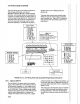
SECTION 9. INPUT/OUTPUT INSTRUCTIONS TABLE 9-1. Input Voltage Ranges and Codes Range Code Fast 16.67ms 250ps Slow Integ. Integ. 1 11 2 3 4 12 13 14 5t* 15*" Resolution FullScale Range t5 +15 t50 t500 t5000 0.33 microvolts millivolts millivolts millivolts millivolts millivolts 1. microvolts 3.33 microvolts 33.3 333. microvolts microvolts ' Differential measurement; resolution for single-ended measurement is twice value shown. ** The lhtegration times for ranges 5 and 15 are 1.
SECTION 9. INPUT/OUTPUT INSTRUCTIONS The count is incremented when the input voltage changes from below 1.5 volts to above 3.5 volts. The maximum input voltage is t20 volts. LOW LEVEL AC This mode is used for counting freqqency of AO signals from magnetic pulse flow transducers or other low voltage, sine wave outputs.
SECTION anywhere almost twice but pulse can be discard mentioned correct this 391 B/392D one second too short to long. Pulses are not lost during so totalized values are correct information such as wind speed twice the correct value. The from excessive intervals option the previous paragraph does not in 21Xs with PROMs earlier. 9.
SECTION 9. PARAM. NUMBER INPUT/OUTPUT INSTRUCTIONS DATA TYPE 01: 2 2 2 02: 03: 04:.
SECTION PARAM. NUMBER PATA [YPE 9. INPUT/OUTPUT INSTRUCTIONS PARAM. NUMBER Repetitions Range code Input channel number for 01: 02: 03: first measurement o4: 2 2 2 2 05: 2 I 02: l22 03: 2 04: 2 01: 05: 06: 4 '4 4 07: 08: 09: iFP Input locatiQns FP DATA TYPE DESCRIPTION Excitation channel number Delay (0.
SECTION 9. PARAM. INPUT/OUTPUT INSTRUCTIONS DATA NUMBER TYPE DESCRIPTION 01: Repetitions Input channel number of first measurement Excitation channel number Input location for first measurement Multiplier Offset 02: 2 2 03: 2 4 05: 06: FP FP Input locations altered: 1 for each thermistor channel Range (%RH) Error (%RH) 10 - 100 t4 15-94 t1 PARAM.
SECTION 9. INPUT/OUTPUT INSTRUCTIONS TABLE 9-3. Thermocouple Type Codes X=0 X=8 Thermocouple Tvpe T (copper - constantan) E (chromel - constantan) K (chromel- alumel) J (iron - constantan) Code X1 x2 X3 x4 X= Normal Measurement 9 TC input from A5B40 isolation (use 5 V range) Output -99999 if out of common mode (lnst.
SECTION 9. INPUT/OUTPUT INSTRUCTIONS **" 17 TEMPERATURE OF INPUT PANEL *** FUNCTION This instruction measures the temperature in degrees Celsius of the input panel. PARAM. NUMBER not the same as the signatures given in the Mode. Recording the signature allows of any program change or ROM failure. PARAM.
SECTION *** 22 EXCITATION WITH DELAY *** FUNCTON ATA YPE 01: 4 02: 4 03: FP o4; Input locati INPUT/OUTPUT INSTRUCTIONS and greater voltage ranges are practical (range codes 13-15). I This instruction is used in conjunction with others for mfasuring a response to a timed excitation using the switched analog outputs.
SECTION 9. INPUT/OUTPUT INSTRUCTIONS trigger when measurement goes from above the limit to below it or when the digital trigger goes from high to low. When triggering on the rising or falling edge, the input must make the specified transition to trigger. For example, when triggering on the rising edge, if the input starts out high, it must go low and then high again to trigger.
SECTION location table. l2 of Instruction 23 in the program by 13 is the multiplier and 14 the offset (to the raw data) determined by the first calibration. I is a fixed value determined by the lected. 15 through ln_2a.re the raw input range data. Thus, the value of the first sent (M1) in millivolts is: Mr = lzlls (ls - 1+) The measurdment data are sent in the order that the measureinents are made (i.e., the first measuremerft for each channel, then the second measuremerft for each channel, etc.).
SECTION 9. INPUT/OUTPUT INSTRUCTIONS B when done measuring. Trigger option 0 - Trigger immediately 1 - Trigger if above limit (high) 2 - Trigger if below limit (low) 3 - Trigger on rising edge 4 - Trigger on falling edge Destination 0 - Input Storage 1 - Serial port 9600 baud 2 - Serial port 76,800 baud Measurement 0 - Ditferential measurement 1 - Single-ended measurement Scan interval(ms, minimum 0.97 x reps, limited to 0.
SECTION *lnput configuration; 4 02: 03: 4 04: 05: 06: 07: 08: 09: 4 4 4 4 FP FP .
SECTION 9. INPUT/OUTPUT INSTRUCTIONS r** 104 SDM-CD16 ..* lf the SW8A does not respond, -99999 will be loaded into input locations. Modules which do not respond when addressed by the datalogger may be wired or addressed incorrectly. Verify that the address specified in Parameter 2 corresponds to the jumper setting and that all connections are correct and secure. See the SDM-SW8A Manual for examples. PARAM.
SECTION 10. PROCESSING INSTRUCTIONS To facilitate qross referencing, parameter descriptions pre keyed I to the values given on the PROMPT SHEET. These values are defined as fdllows: [Z] = User sflecified input location number destination [X] = Input ldcation no. of source X [Y]= Input lqcation no.
10. PROCESSING INSTRUCTIONS SECTION *** 36 XrY *** PAR. DATA FUNCTION Multiply the value in location X by the value in location Y and place the result in location Z. NO. TYPE DESCRIPTION 01: 02" Input location of X Dest. input location for X1/2 4 4 Input locations PAR. DATA NO. TYPE DESCRIPTION 01: 4 02: 4 03: 4 lnput location of altered: *** 37 X*F 1 *** 40 LN(X) *** X Input location of Y Dest.
SECTION 10. PROCESSING INSTRUCTIONS *** 43 ABS(X) **' FUNCTION Take the abbolute value of the value in location X and placelthe result in location Z. 02: NO. TYPE DESCRIPTION 01: Q2: 03: Input location of txl Fixed [F] Dest. input location for X MOD F 4 FP 4 lzl PAR. DATAI NO. TYPEi 01: PAR. DATA Input locations DESCRIPTION lnput locatiofrs altered: 1 *** 4i[ FRACTIONAL VALUE *** altered: 1 *** 4T ;1Y *** X Input location of tX1 Dest.
SECTION 10. PROCESSING INSTRUCTIONS Parameter 3 cannot be entered as an indexed location within a loop (lnstruction 87). To use Instruction 49 within a loop, enter Parameter 3 as a fixed location and follow 49 with Instruction 31 (Move Data). In Instruction 31, enterthe location in which 49 stores its result as the source (fixed) and enter the destination as an indexed location. PAR. DATA NO. TYPE 01: 02: 03: Swath lswA Starting input location [1ST Dest.
SECTION 10, PROCESSING INSTRUCTIONS' Computation of Saturation Vapor Pressure. J. Appl. Meteor. 16, 100-103. PAR. DATA NO. 01: 02: 03: 04: 05: TYPE 4 4 2 4 2 DESCRIPTION Number of values to move 1st source location Step of source 1 st destination location Step of destination Saturation vapor pressure over ice (SVPI) in kilopascals for a OoC to -50oC range can be obtained using Instruction 55 and the relationship SVPI= -.00486 + .85471X+ .
SECTION 10. PROCESSING INSTRUCTIONS *** 59 BRIDGE TRANSFORM '** PAR. DATA NO. TYPE DESCRIPTION 01: 4 Input location no. of atmospheric pressure in kilopascals IPRESSURE] Input location no. of dry-bulb temp. IDB rEMP.l lnput location no. of wet-bulb IWB TEMP.] Dest. input location for vapor pressure [VP or Z] FUNCTION 02: 4 03: 4 04: 4 temp.
SECTION 10. PROCESSING INSTRUCTIONS amount of do not at the different frequencies but any phase information. originaltime varying signalcan be by taking the Inverse Fourier magnitude ahd phase results. PROGRAMMING The FFT Instruction is a Processing Instruction and will not dutput data to final memory or any data storage device. FFT results are transferred to Final Meniory by setting the Output Flag and sampling thQ input locations which contain the FFT results.
SECTION 10. PROCESSING INSTRUCTIONS power spectral is output. Parameter 3 is equal to the log base 2 of A where A is the number of bins to be averaged. For example, if there are 1024 samples in the originaltime series data and the resulting 512 spectral bins are averaged in groups of 8 (Parameter 3 = 3 = log base 2 of B) then 63 (=5724 1) averaged bins will be produced. PARAMETER 4 defines which input location will contain the first value at the original time series data.
SECTION 10. PROCESSING INSTRUCTIONS' where the magnitude is half of the zero to peak amplitude or one quarter of the peak to peak value of the sinusoidal signal. or one quarter of the zerc to pea peak to value of the sinusoidal signal. AND PHASE COMPONENTS MAGN The result of the FFT when the magnitude and phase optiori is selected is N/2 input locations containing tlp magnitude components (Mi) followed by llli2 input locations containing the phase comppnents (P1).
SECTION 10. PROCESSING INSTRUCTIONS For example, given that the power spectra result shows that the energy peak of a signal falls in bin 32 when it is sampled at a frequency of 10 Hzlor 1024 samples and that the bin averaging specified is 4, the frequency of the signal in bin i is: 31 * 10 " 4 / 1024
SECTION 10. PROCESSING INSTRUCTIONS *** INDEXED MOVE *** 61 FUNCTION from location X to location Y, Moves input where X and Y are indirectly addressed. The values of thd location numbers X and Y are stored in the locations specified by Parameters 1 and 2. The 21X looks in the locations specilied in the parameters to find the locations to use as the source and destination of the data.
SECTION 10. PROCESSING INSTRUCTIONS TABLE 10-2. Maximum Number of Outputs and Output Order for K lnput Values. (The output order flows from left to right and from top to boftom) INPUTS: X1 )<2 X3 x4 XK (1st) (2nd) (3rd) OUTPUTS (4th) (Kth) MAX NO. TYPE OUTPUTS Means K M(X1) M(x2) M(x3) M(x4) M(XK) Variances K V(X1) v(x2) v(x3) v(x4) v(xK) Std.
SECTION 10. PROCESSING INSTRUCTIONS phase is where new input ived, the necessary squares or formed, and the appropriate summation calculated as required by the desired fina output. The rate at which the can be made, the input values The Input values are completed v{tithout i nterruption dete rmi nes the maximum r4te of execution (see Execution Time). The Averagfng Period Processing occurs whenever tfte number of input samples entered in Parametdr 7 is satisfied or whenever an Output Intertval occurs (i.
SECTION 10. PROCESSING INSTRUCTIONS N' is the number of input scans in the last averaging period NT is the total number of input samples processed in the Output Interval INTERMEDIATE STORAGE REOUIREMENTS The number of Intermediate locations will depend upon the number of input values and outputs desired: 1. 2. 3. 4, Define K as the number of input values.
ON 11. OUTPUT PROCESSING INSTRUCTIONS 69 WIND VECTOR *'* FUNCTION Instruction 6p processes the primary variables and direction from either polar (wind speedland direction) or orthogonal (fixed propellers) sensors. lt uses the East and the mean wind speed, the raw data to magnitude, and the mean mean wind wind vector flirection over an output interual. Two differer* calculations of wind vector direction (and standard deviation of wind vector direction) arg available, one of which is weighted foqwind speed.
SECTION 11. OUTPUT PROCESSING INSTRUCTIONS There are three Output Options, which specify the values calculated. where Ux=(Xsin Option 0: @;)/N Uy=(Xcos O;)/N Mean horizontalwind speed, S. Unit vector mean wind direction, @1. Standard deviation of wind direction, o(@1). or, in the case of orthogonal sensors Ux=(x(Ue;/U;))/N Uy=(E(Un/Ui))/N Standard deviation is calculated using the Yamartino algorithm.
SECTION 11. OUTPUT PROCESSING INSTRUCTIONS ** 71 AVERAGE *** information, which is selected by entering the appropriate code for Parameter 2. FUNCTION This instructibn stores the average value over the given oulput interualfor each input location PAR. DATA NO. TYPE specified. 01: PAR. DATA 02: NO. 03: ryPE DESCRIPTION 01: 2 | Repetitions 02: 4 Starting input location no.
SECTION 11. OUTPUT PROCESSING INSTRUCTIONS (defined as the bin select value) is within a particular subrange of the total specified range. The count in the bin associated with each subrange is incremented whenever the value falls within that subrange. The value which is output to Final Storage for each bin is computed by dividing the accumulated total in each bin by the total number of scans: This form of output is also referred to as a frequency distribution.
SECTION 11. OUTPUT PROCESSING INSTRUCTIONS it is the first firinute of the day. Similarly, entering 2 fof the hour-minute code causes 2400 instead of 0QO0 to be output (the next minute is still 0001). When day and hour-minute are both output, a 2 tdr either code results in the previous day at 2400. The year is Qutput as 19xx if xx is greater than 85, otherwis€ it will be output as 20xx. The 21X will require a PROM update in the year 2085.
SECTION 11. OUTPUT PROCESSING INSTRUCTIONS The output flag must be set each time Instruction 80 is used. Instruction 80 must directly follow the instruction that sets the output flag. PAR. DATA NO. TYPE 01: 2 Q2: 4 DESCRIPTION * Storage area option o' = :ll3'o?',:'f, f i"(Pi.
SECTION 11. OUTPUT PROCESSING INSTRUCTIONS More than ofre Rainflow Histogram can be calculated u$ing the Repetitions parameter. The swath of inpirt data, the size of the mean and amplitude difnensions, the low and high limits of the input datla, and minimum distance between peaks and v6lley are all selectable by the user with paramelers. *** 82 STANDARD DEVIATION IN TIME *** FUNCTION Calculate the standard deviation (STD DEV) of a given input location.
N 12. PROGRAM CONTROL INSTRUCTIONS 12-1. Flag Description Output Flag Flag 0 Flag 1 to 8 Flag 9 User Flags I ntermediate Processing Disable Flag TABILE 12-2. Command Codes 01-9, 77-99 1 0-tr9 20-49 g0 31 32 Go to end of program table Call Subroutine 1 -9, 77-99 Set Flag 0-9 high Set Flag 0-9low Then Do Exit loop if true Exit loop if false Setport1-6high Setportl-6low Toggleport1-6 41-46 51-q6 61 Instruction 95, END. Allsubroutines must be placed in Table 3 (Subroutine Table).
SECTION 12. PROGRAM CONTROL INSTRUCTIONS A delay of 0 means that there is no delay between passes through the loop. Each time the table is executed all iterations of the loop will be completed and execution will pass on to the following instructions. lf the delay is 5, every fifth time that the execution interval comes up, one pass through the loop is made; only those instructions in the loop will be executed and other portions of the table are not executed in the interim.
SECTION 12. PROGRAM CONTROL INSTRUCTIONS t hour averages of the vapor lated from the wet- and dry-bulb of 5 psychrometers. One pressure measurement is also available for pse in the vapor pressure calculation. The user pressure 1. The inpuf locations are assigned as follows: a) presspre b) dry-bqrlb temperatures c) wet-blrlb temperatures d) calcufbted vapor pressure - location 10 location 1 1-15 location 16-20 location 16-20 (vapof pressure is written over the wet- bulb temperatures.) 2.
sEcTtoN 12. PROGRAM CONTROL INSTRUCTIONS 12: 01: 02: 03: 04: 13: 14: 01: 02: P89 25 3 6 31 *T* lf X<=>F X Loc DAY FUNCTION Exit Loop if true Beginning of Loop Delay Loop Count 1 *** This instruction compares two input locations and, if the result is true, executes the specified Command. The comparison codes are given in Table 12-5. P87 27: P86 01: 28: P89 01: 25 O2: 3 03: 16 04: 31 Y F End 0 IF X COMPARED TO >= P95 1 88 PAR.
SECTION 12. PROGRAM CONTROL INSTRUCTIONS I the loop. ln$truction 90 does not affect the loop counter whi{r still counts by 1. I PAR. DAT4 NO. TYPE DESCRIPTION 01:2 Increfnent PAR. for the loop index counter **{ 91 IF FLAG, PORT *** FUNCTION This instructfon checks one of the ten flags or 8 ports and coyrditionally performs the specified command. The high inp;rt of any differentialchannel may be used to sen$e the status of a logic signal (3 Vchigh
SECTION 12. PROGRAM CONTROL INSTRUCTIONS the start of the instructions to execute if the test condition is false (Figure 3.8-1). The Else Instruction is optional; when it is omitted, a false comparison will result in execution branching directly to the End Instruction. Instruction 94 has no parameters.
SECTION 12. PROGRAM CONTROL INSTRUCTIONS When eitherlthe DC112 or RF modem options are specifie{ the time limit on the call (without a correct respdnse) specified in Parameter 3 is timed from tile start of the instruction and must include the daling time. lf the call is to go through a RF link to a phone, then the RF Modem is specified in Parameter 1. A RF Modem must be used between the DCSS and the phone line. See the PC208 manualfor additional interfacing notes.
SECTION 12. PROGRAM CONTROL INSTRUCTIONS *** 98 SEND CHARACTER *** Instruction 98 is used to send a character to the printer. The single parameter sets the baud rate and gives the decimal equivalent of the 7 bit character (sent as 8 bits, no parity). For example, to send the ASCII character control R at 9600 baud, 2018 would be entered for Parameter 1. This instruction can be used to send a control character to activate some device.
SECTION 13. 21X MEASUREMENTS Setup Amplifier Iniegrotion AfD 13.1 FAST A {D SLOW MEASUREMENT Conversion Settling SEQUENGE ' The 21X malkes voltage measurements by integrating tfie input signal for a fixed time and then holding the integrated value for the analog to digital (A/0) conversion. The A,/D conversion is made with a 14 bit successive approximation technique wflich resolves the signal voltage to approximately one part in 15,000 of the full scale range pn a differential measurement (e.9.
SECTION 13. 21X MEASUREMENTS averaging the magnitude of the results from the two integrations and using the polarity from the first. An exception to this is the differential measurement in Instruction 8 which makes only cannot be made because the high input is outside of the common mode range. (The 21X will indicate the overrange with the maximum negative number, see Section 3.5.) one integration. Setup Amplifier Integrotion A/D Conversion Settling 450 uS fost 250uS 16.
SECTION 13. 21X MEASUREMENTS 13.3 THE EF ECT OF SENSOR LEAD LENGTH TIME N THE SIGNAL SETTLING Whenever an analog input is switched into the 21X measurdment circuitry prior to making a measuremedt, a finite amount of time is required for tfe signal to stabilize at its correct value. The ralte at which the signal settles is determined by the input settling time constant which is a function of both the source resistance, ahd input capacitance (explained below).
SECTION 13. 21X MEASUREMENTS NOTE: Since the peak transient, V"o, causes significant error only if it is several times larger than the signal, V"o, error calculations made in this section approximate V'"o by V"o; i.e., V'"o = V"o. lf the input settling time constant, t, is known, a quick estimation of the settling error as a percentage of the maximum error (V.o for rising, V'"o for decaying) is obtained by knowing how many time constants (Vt) are contained in the 450ps 21X input settling interval (t).
SECTION 13. 21X MEASUREMENTS SHIELD DIELECTRIC ABSORPTION The dielectric absorption of insulation surrounding individual conductors can seriously affect the settling waveform by increasing the time required to settle as compared to a simple exponential. Dielectric absorption is difficult to quantify, but lt can have a serious effect on low level measurements (i.e., 50mV or less). The primary rule to follow in minimizing dielectric absorption is: AVOID PVC INSULATION around conductors.
SECTION 13. 21X MEASUREMENTS Equation 13.3-12, -13 and -14 can be combined to estimate the error directly in degrees at various directions and lead lengths (Table 13.33). Constants used in the calculations are given below: the 21X. The lead wire is a single-shielded pair, used for conducting the excitation (V,) and signal (Vr) voltages. When V, is switched on, a transient is capacitively induced in V", the signal voltage.
SECTION 13. 21X MEASUREMENTS 1) Veo = 100mV, peak transient Equation 13,13-7 can be solved for the maximum lead length, l, permitted to maintain a specified error limit. Qombining Equations 13.3-7 and 13.3-4 and splving for L gives: 1- = -(RoC1+ (Vln(V"A/"o)))/RoC* at 4V excitation 2) V" = SltV, allowable measurement error 3) t = 4501rs, 21X input settling time [13.3-15] where V" is the measurement error limit. 4) Ro EXAMPLE I-.
SECTION 13. 21X MEASUREMENTS lead length. lf the capacitive load exceeds 0.1 pfd and the resistive load is negligible, V, will oscillate about its control point. lf the capacitive load is 0.1 pfd or less, V, will settle to within O.1o/o ol its correct value in 150ps. A lead length of 2000 feet is permitted for the Model 227 betore approaching the drive limitation. Table 13.3-6 summarizes maximum lead lengths for corresponding error limits in six Campbell Scientific sensors.
SECTION 13. 21X MEASUHEMENTS Use the 1X to measure the input settling with a given configuration. error For e assume long leads are but the lead capacitance, C*, is Configure Rl on a length of cable similar td the measurement. Leave the sensor {nd open as shown in Figure 13.3-8 and me{sure the result using the same instructiOn parameters to be used with the sensor. The measured deviation from 0V is the input settling error.
SECTION 13. 21X MEASUREMENTS = A) Ro r\ | = - Jvt\ vtilvl RsRf/(Rs+Rf), Vs = VxRf/(Rs+Rf) FIGURE 13.3-9. Incorrect Lead Wire Extension on Model 107 Temperature 13.4 THERMOCOUPLE MEASUREMENTS B) Ro@P = ns(Rf+Rf)/(Rs+Rf+Rf) SHITLD = JOK OHM | \l : C) Ro = Rf, Vs = VxRf/(Rs+Rf+Rf) FIGURE 13.3-7.
SECTION 13. 21X MEASUREMET{TS is emphasized that this is the worst case. In Campbell Scientific's experience, the overall accuracy is typically better than t0.2oC. The major error component in the -35oC to +50oC range is the +0.2oC thermistor specification. When a21X is outside of this temperature range, the polynomialerror becomes much worse (Figure 13.4-1), and may necessitate the use of an external reference junction to improve the accuracy. polynomial approximation of the NBS TC calibrations. l 13.4.
SECTION 13. 21X MEASUREMENTS THERMOCOUPLE LIMITS OF ERROR The standard reference which lists thermocouple output voltage as a function of temperature (reference junction at OoC) is the National Bureau of Standards Monograph 125 (1974). The American National Standards Institute has established limits of error on thermocouple wire which is accepted as an industry standard (ANSI MC 96.1, '1975). Table 13.
SECTION 13. 21X MEASUREMEI{TS of 0.05% error of appropriate the voltage of a degree. is 25pV which is a temperature O.6oC. In the environmental with voltage measured on an error in temperature due to rements is a few hundredths THERMOCQUPLE POLYNOMIALS: Voltage to Temperafure NBS Monogfaph 125 gives high order polynomials for computing the output voltage of a given therinocouple type over a broad range of temperatqres.
SECTION 13. 21X MEASUREMENTS built-in thermistor. Errors in the thermocouple and reference temperature polynomials are extremely small, and error in the voltage measurement is negligible. To illustrate the relative magnitude of these errors in the environmental range, we willtake a worst case situation where all errors are maximum and additive. A temperature of 45oC is measured with a type T (copper-constantan) thermocouple, using the *SmV range. The nominal accuracy on this range is 2.5pV (0.
SECTION 13. 21X MEASUREIT,IENTS allof the bridge measurements make one set of FIGURE tg.4-2. Diagram of Junction Box An external reference junction box must be constructed so that the entire terminal area is very close tO the same temperature. This is necessary sO that a valid reference temperature can be measured. and to avoid a thermoelectric otfset voltagB which will be induced if the terminals at Which the thermocouple leads are connected (points A and B in Figure 13.
SECTION 13. 21X MEASUREMENTS INSTR. DIAGRAM = RESULT DESCRIPTION X # vx DC HALF BRIDGE vl WITH USER ENTERED X = Vr = Vx Rs+Rr SETTLING TIME BRIDGE V' R. X= = K5*f(1 =-= POLARITY FOR ION -vx AC HALF EXCITATION ALTERNATES DEPOLARIZATION 4 WIRE FULL BRIDGE 3 WIRE X = v_-=- HALF BRIDGE looo + = tooo (f-3 +R1 2V2- V1 R5 Vx-v1 Rr v2 6 WIRE FULL BRIDGE = 1000q = 1000 WITH EXCITATION LEAD COMPENSATION 4 WIRE HALF BRIDGE ( v, olr 5 v V2 =-=Vr ,RrR2\ t-p, .. n.
SECTION 13. 21X MEASUREMENTS 3 Wire *Vx Half Bridge Compensates for lead wire resistance, assuming resistance is same in both wires. Two single-ended measurements at each excitation polarity. Ratiometric output. I 123456 Time Differential Measurement with Excitation Makes a ditferential measurement without reversing excitation polarity or switching inputs. Used for fast measurements on load cells, PRTs etc. Resolution and common mode rejection worse than 6 if used with delay=g.
SECTION 13. 21X MEASUREMENTS TABLE 13.5-2. Calculating Resistance Values from Bridge Measurement lnstr. 4 Result Instr. Muttiplier X=Vx(Rs/(R"+R1)) x /v_ ' I rf -- 1 ((x 59. Mult. = 1A/"; ofs. = Mult. = Rr 4. 59. Mult. = 1A/"; ofs. = 0 Mult. = 1/Rs 4. R" =Rt - '1-X/Vx 5 and Offset tv)t(1-x/vx))/Rs O 42. X=Rr/(R"+R1) X 5. R"=Rt- '1-X 59. 5. 1 Fl{ =- ' (xt(1-X))/Rs 59. Mult. = 1; ofs. = 0 Mult. = 1/R"; ofs. = 0 42.
SECTION 13. 21X MEASUREMENTS 13.6 RESIST REQU CE MEASUREMENTS AC EXCITATION sensors require AC excitation. lhe 207 relative humidity probe, Some These water conductivity sensors, grids. The use of DC soil and wetness polarization, which willcause an erroneous measurement, and may shift the calibration of the sensor arhd/or lead to its rapid decay.
SECTION 14. INSTALLATION AND MAINTENANCE FROM THE 14.1 ENVI tal variables of concern and moisture. The standard 21X is designed to operate reliably from -25 to +SOoC (-55 to +80oC, optional) in noncondenging humidity. When humidity tolerances 4re exceeded, damage to lC chips, microprocegsor failure, and/or measu rement inaccuracie$ due to condensation on the various PC board runners may result. Etfective humidity coftrol is the responsibility of the user.
SECTION 14. INSTALLATION AND MAINTENANCE 14.2 POWER REQUIREMENTS The 21X operates at a nominal12V DC. Below 9.6 or above 16 volts the 21X does not operate properly. The 21X is diode protected against accidental reversal of the positive and ground leads f rom' the battery. Input voltages in excess of 18V may damage the 21X and/or power supply. A transzorb provides transient protection by limiting voltage at approximately 20V.
SECTION 14.9 21X PqWER SUPPLIES I The 21X is {vailable with both alkaline batteries (21X) and lepd acid batteries (21XL). The difference b6tween the 21X and 21XL is the power supplf base. Converting from a 21X to 21XL or vics versa can be done by simply purchasing he appropriate base. 14.3.'1 21X ALKALINE POWER SUPPLY The 21X utilizes I alkaline D cells. Two screws must be from the front panel to install the see Figure 14.3-1.
SECTION 14. INSTALLATION AND MAINTENANCE TABLE 14.3-2. 21XL Battery and AC Transf ormer Specif ications Lead Acid Battery Battery Type Float Life @ 25oC Capacity Shelf Life, fullcharge Charge Time (AC Source) Gates #810-0011X 8 years minimum 2.5 amp-hour Check twice yearly 40 hr full charge, 2O hr 95o/" charge AC Transformer 120V AC, 60 Hz 20V DC @ 350 mA Input: lsolated Output: max. There are inherent hazards associated with the use of sealed lead acid batteries.
SECTION 14. INSTALLATION AND MAINTENANCE medium power transistor), the use of a relay (Figure 14.7-1) would be required. Vehicle +12 Vehicle + lOC MAXIMUM MAXIMUM CURRENT TO PERIPHERAL lS 75 mA AT 25t, 40 mA AI -50t FIGURE 141.6-1. Connecting Vehicle Power I Supply coNlR0t PORI 14.
SECTION 14. INSTALLATION AND MAINTENANCE damage the datalogger. Campbell Scientific's DC112 phone modem has spark gaps on the phone lines. A 12 AWG wire should be run from the modem ground terminalto earth ground. power grounds are at the same potential. To safe, the ground of allthe AC sockets in use should be tied together with a 12 AWG wire. 14.9 MAINTENANCE The 21X requires a minimum of routine rnaintenance.
SECTION procedures are for calibrating the and the clock. Other factors ratios, DAC non-linearity, and r the switched excitation or the offset in CAO voltage require that the 21X be returned to repair. Please callthe factory to the factory :ation before sending in the unit. obtain The 14. INSTALLATION AND MAINTENANCE 3. Monitor the Digital to Analog Conveder (DAC) output by connecting the positive lead of the DVM to the DAC OUTPUT TEST POINT which is the left side of the 3.
SECTION 1. 14. INSTALLATION AND MAINTENANCE Remove the 21X battery base and unplug the battery from the 21X. Remove the four screws holding the aluminum cover plate and remove the cover plate. Lay the 21X, shown at Location P10 on Figure 14.10-2. Connect the ground lead to any one of the capacitor leads circled in the upper left corner of Figure 14.10-2. Adjust the variable capacitor at location 516 for a period of 49999.0 microseconds (20 ppm fast) or 50000.0 microseconds (exactly on).
SECTION tt' 14. INSTALLATION AND MAINTENANCE I td' *ffiqgffiililH F$ffik H ffift; ffil lc - 5i trg?'rrlirq F-T8f--lfTt ; @ Qa Ji :;q I rll:ll :l lF.1i."J @ H *o?++tffi+ffiHHFnffi ep @ @ @firFff,qD:7fl.-lu.l-11ff,-.' ;:; $ftffi$ftffift r ffi H[HHH[d,liJ ,:u! J o€ i< or9 o '. F - a> , ll;l :l16l 1bE Es Il.r*-1 -,3. . I d ffffi$'THmHHHH 4't ffd-:fiil r-lg.gilJ 'F-ir-i-ili [l1- I '61' ( I .t- '.r .t.r [-H-i.!l-ij R'l .li d l ' ,rcuRE 14.1o-2.
APPENDIX for American Standard nformation Interchange "askee"). A specific binary code of 28 characters represented by 7 bit ASCII: Code fo I binary BAUD RATE: The speed of transmission of informatibn across a serial interface, express{d in units of bits per second. For examplef 9600 baud refers to bits being transmittpd (or received) from one piece of equipmefrt to another at a rate of 9600 bits per secofrd.
APPENDIX A. GLOSSARY INTERMEDIATE STORAGE: That portion of memory allocated for storing the results of intermediate calculations necessary for operations, such as averages or standard deviations. Intermediate storage is not accessible to the user. LOW RESOLUTION: This is the default output resolution.
APPENDIX A. GLOSSARY : A number which is a function of nd the sequence of data in memory.l lt is derived using an algorithm which a*ures a 99.998% probability that if SIGNATUR the data either th* data or its sequence changes, the signaturO changes. THROUGHFUT: The throughput rate is the rate at which a measurement can be made, scaled tq engineering units, and the reading stored inl Final Storage. The 21X has the ability to]scan sensors at a rate exceeding the thro{ghput rate (see SAMPLE RATE).
APPENDIX B. PROM SIGNATURES AND SOFTWARE OPTIONS .B Mode and advancing to the appropriate signatures are viewed by entering the 2.4.3.). The 21X uses three PROMS. The third PROM determines the PROM option. ROM signatures are given in Table B-1. The 21X P window ( The current TABLE 8.1. 21X PROM SIGNATURES OPTION SIGNATURE PROM VERSION REVISION 02:14441. 03:14436. or 03:5872.0" osx-o.1 04:50721. 08:.10000 09:0005 osx-1.1 04:866.00 08:1.1000 09:0004 osx-2.1 04:44109. 08:2.1000 09:0005 .
APPENDIX C. BINARY TELECOMMUNICATIONS but remains set once set until reset by another J command or telecommunications MUNICATIONS WITH BINARY is terminated. S The remaining bits are reserved. Description [no. of loc.]F I BINARY DUMP - 21X sends, in Final Storage Format (binary, the number of Final Storage locations specified (from current MPTR locations), then Signature (no prompt). 4) lf the 2nd MSB in "b" was set then "c" is a port toggle byte, otherwise "c,d,...
APPENDIX C. BINARY TELECOMMUNICATIONS previously executed; four time bytes, a user flags byte, four bytes for each input location requested in the J command, Final Storage data in Campbell Scientific's binary format if requested by the J command, and terminating in 7F 00 HEX and two signature bytes.
APPENDIX c.2 i C. BINARY TELECOMMUNICATIONS second F|NAL STORAGE FORMAT I 21X data is fprmatted as either 2 byte LO Resolution oi 4 byte Hl Resolution values. The first two byteb of an output array contain a code noting the stfrt of the output array and the output array lD, followed by the 2 or 4 byte data values. At the end of the data sent in response to the telecommunications F command a 2 byte signature is gent (see below).
APPENDIX C. BINARYTELECOMMUNICATIONS HIRESOLUTION FORMAT Continuing to use the A-H bit representation, the four byte number is shown below as two two byte pairs. ABO111GH XXXXXXXX OO1111GH XXXXXXXX BITS, 1ST BYTE, lST PAIR DESCRIPTION CDEF=0111 Code designating 1st byte pair of four byte number. B Polarity,0=+, 1=-. G,H,A, Decimal locator as defined below. 2nd byte 16th - gth bit (left to right) of 17 bit binary value. ABCDEF=001111 Code designating 2nd byte pair of four byte number.
APPENDIX lr | It'' 3. C. BINARY TELECOMMUNICATIONS ,r = Sr(n) S1(n+1)= So(n) I Form a tpmporary byte by shifting the old low sign{ture byte one bit to the left and adding afy carry bit which results from the shift opefation. A "shift left" is identicalto a multiply $y 2. lgnore any carry bit resulting from the hdd. T2 = shift left (Ss(n)) + carry 4. Form the new low signature byte by adding the results of operation 3 to the old high signaturE byte and the transmitted byte.
APPENDIX D. ASCII TABLE American Standard Code for lnformation lnterchange Decimal Values and Characters (x3.4-1e68) Dec. Ghar. 0 CONTROL @ OONTROL A CONTROL B CONTROL C OONTROL D 1 2 3 4 5 6 7 8 9 10 11 12 13 14 15 16 17 18 19 20 21 22 23 24 25 26 27 28 29 30 31 Dec. Char. Dec.
APPENDIX E. CHANGING RAM OR PROM CHIPS (An@ 9lttps The 21X has sockets for memory chips. Five sockets hotd 8K Random Access Memory PROM two have may 21Xs Older prigi^^"firc chips. tttemory neid Onty FROM) and three ho chips and as 'ew as two RAM chiPs. E.l DISASSETI'IBLY OF 21X 1. Turn pourcr off, remove the two Phillips head scr4ws located near the edges of the front pan$l of the micrologger. Carefully lift the microfogger up and away from the battery P{ck and disconnect the plastic power cofnector.
APPENDIX E. CHANGING RAM OR PROM CHIPS The earliest 21Xs were shipped with only two 4K RAM chips. Current software does not check for this condition; if an old 21X is being upgraded to new sottware PROMS, five 8K RAM chips (CSl Modelnumber EMXS) should also be installed. The older 21X has iumpers at locations M15, W2O, and W27 (Figure E-l). With 8K RAM chips installed, Ml5 should be jumpered on the right set of pins and W20 and W27 should be jumpered on the left set of Pins.
t I I I I I APFENDIX F.
*D TAPE UPLOAD AND DOWNLOAD FUNCTION This library qption adds additional*D mode commands that allow datalogger programs to be saved to {nd loaded from a cassette tape. (Command 1). The C20, with the format switches in the "ll, Decode" position, will read the file. The PC201 will read the file if the TAPE.COM program is run and the File Data Format is specified as either Printable ASCII or Comma Delineated ASC|l.
LIST OF TABLES PAGE * ti4ode Summary.... ""r-",=L ov3-1 Functions...........:;......... Instructions Manual ov3-2 ovs-1 ov5-2 1. K$y Description/Editing DAta Retrieval Methods and Related Data Retrieval Sections in FUNCTIONAL MODES Mode Commands 21X............ Data........... Data........... Codes. Commands Codes......... Codes 1.................
LIST OF TABLES 6. 9 PIN SERIAL INPUT/OUTPUT 6.1-1 6.5-1 DTE Pin Configuration................. 8. PROCESSING AND PROGRAM CONTROL EXAMPLES Offset Locations.... Assi9nments................. Example Sensor Description and 21X Multiplier and ............8 Example Outputs and Input Storage .........8 Example Input Channeland Location ........8 Thirty Minute Output From Examp|e.............. .............8-11 FFT Real and lmaginary Results 0.25 and 1.25 Hz Signal ............
LIST OF TABLES 14. INST LLATION AND MAINTENANCE 14.2-1 14.3-1 14.3-2 14.4-1 Peripherals............. .......... 12 LA Battery and AC Transformer Specifications X5 and MSX10 Solar PanelSpecifications................. APPENDIX B-1 .'....... 14-1 ical Current Drain for Common 21X icatAlkaline Battery Service and Temperature B. .............. 14-3 ..'.'............". 14-3 '.'-.-.-.'..'.14'4 21X PROM SIGNATURES AND SOFTWARE OPTIONS 21X PROM Signatures ..........'.8-1 LT.
LIST OF FIGURES PAGE "t=r",=L 21[ Micrologger........... OV1-1 ........OV-1 oV1-221XWiringPanelandAssociatedProgramminglnstructions.'.'............. OV2-'l In$truction Types and Storage Areas ....'. OV-4 ..'.......... OV-6 ... OV-17 OV2-2 Prpgram and Subroutine Tables OV5-1 D4ta Retrieval Hardware Options....... 2. INTERNAL DATA STORAGE Ring Memory Representation of Final Data Otftput Array 2.1-1 1D...... 2.1-2 3. ..................2-1 ......'...........2-1 INSTRUCTION SET BASICS 3.8-1 3.
LIST OF FIGURES 13. 21X MEASUREMENTS 13.1-1 13.2-1 13.3-1 13.3-2 13.3.3 13.3-4 13.3-5 13.3-6 13.3-7 13.3-8 13.3-9 13.4-1 13.4-2 13.5-1 13.5-2 13.6-1 13.6-2 14. INSTALLATION AND MAINTENANCE 14.3-1 14.6-1 14.7-1 14.7-2 14.10-1 14.10-2 APPENDIX E-1 LF.2 E.
21X * Modes, TNDEX Average - flnstruction 711 11-1 Modes 421 1O-2 Probe 1,(l 101 Programming example OV-l3 Computing running 8-1 example 7-11 Probe finstruction 111 9-5 exampfes 7-2,7-12 107 B Battery power options Alkaline D cells 14-2 External 14-4 Lead acid pack 14-3 Solar panels with 21XL 14-4 Vehicle power supply 14-4 Battery Voltage - |nstruction 101 9-5 Baud rate ov-3 12V 207 Relative Humidity Probe finstruction 12] 9-6 Prograffiing example 7-3 227 Soil Moibture Block Prograrnming exampl
21X INDEX Clock CPU card circuitry calibration 14-7 Setting/displaying time ("5 Mode) 1-2 Programming example OV-14 CM6/CM10 Tripod grounding protection 14-6 Common mode range 13-2, 14-6 Communicating with the CR10 Display Pointer (DPTR) 2-1 Displaying/setting Clock ("5 Mode) 1-2 Divide X / Y flnstruction 381 10-2 X Mod F flnstruction 46] 10-3 DO flnstruction 861 12-1 Programming example OV-l0 Wa telemetry 5-1 With external peripherals 4-1 Protocol/Troubleshooting 6-4 Compiling 1-2 Errors 3-9 Computer B
21X INDEX Redirec{ing data flnstruction 801 11-5 exa{nple 8-3 Ring m{mory 2-1 Flags 3-3 nitiate Telecommunications [lnstruction 97] 12-6 Input Storage Altering 1-2 1 Displayi(rg and toggling 1-2 Interme{iate Processing Disable 3-3 Manually toggling (.
21X TNDEX Low Pass Filter ftnstruction 58] 10-6 Low resolution 2-2 LP Filter flnstruction 581 10-6 Lysimeter, weighing 7-8 Output Array Calculating data points 4-2 Definition M Maintenance and installation of the 21x 14-1 Manually initiated data transfer (*8 and *9 Modes) 4-2 Maximum flnstruction 731 11-3 Programming example OV-14 Memory Allocation 1-4 Automatic RAM check on power-up 1-4 Changing RAM or PROM chips E-l Description of areas OV-3 Erasing all 1-5 Pointers 2-1 Minimize flnstruction 74] 11-
21X TNDEX Program RealTime finstruction 77] 11-4 Programming example OV-13 lnstructions 12-1 ov-5 Reference junction Compensation 13-10 Relays, Using digital ports for switching 14-5 Relative Humidity Probe,207 RH Probe flnstruction 121 7-3, 9-6 Remote Keyboard State 5-3 Repetitions parameter 3-1 Resetting 21X 1-5 Resistance measurements requiring AC excitation 13-19 Resolution Final Storage 2-2 Retrievaf options, Data storage OV-17 RH (207) flnstruction 121 7-3,9-6 Ring memory code parameter 12-1 3-4
21X TNDEX Serial InpuVOutput Interface details 6-l External peripherals 4-1 Telecommunication 5-1 Area flnstruction 80] 11-5 Set Active Output Programming examples 8-2, 8-3 Set Resolution Data FinalStorage Format [Instruction 78] 11-5 Sign, Changing number 3-1 Signal settling time, Effect of sensor lead length on 13-3 Signature PROM 1-6, B-1 Generation of C-4 Move Signature into Input Location finstruction 19] 9-8 Sin(X) flnstruction 481 10-3 Programming example 8-13 Single-ended Volts flnstruction 1] 9
21X TNDEX V Vapor Presture From Wet-/Dry-Bulb Temperdtures finstruction 57] 10-5 Prograntming example 8-l 0 Vehicle powFr supply 14-4 Volts (SE) ilnstruction 1l 9-1 Volts (Diff) $nstruction 21 9-1 Z=X+ F ilnstruction 341 10-1 Z=X* Y flnstruction361 10-2 Z=X+ Y ilnstruction 331 10-1 Z=X- Y flnstruction 351 10-1 Z=X /Y ilnstruction 381 10-2 F ilnstruction 46] 10-3 Z --XY flnstruction 471 10-3 Z=Z+ 1 finstruction 321 10-1 Z = X MOD Voltage me{surements Differenlial/single-ended 13-l Integratipn 13'1 lnst