ENC10/12, ENC12/14, ENC14/16, ENC16/18 Revision: 7/11 C o p y r i g h t © 2 0 0 6 - 2 0 1 1 C a m p b e l l S c i e n t i f i c , I n c .
Warranty and Assistance PRODUCTS MANUFACTURED BY CAMPBELL SCIENTIFIC, INC. are warranted by Campbell Scientific, Inc. (“Campbell”) to be free from defects in materials and workmanship under normal use and service for twelve (12) months from date of shipment unless otherwise specified on the corresponding Campbell invoice. Batteries, fine-wire thermocouples, desiccant, and other consumables have no warranty.
Enclosures Table of Contents PDF viewers note: These page numbers refer to the printed version of this document. Use the Adobe Acrobat® bookmarks tab for links to specific sections. 1. General Description.....................................................1 1.1 Specifications............................................................................................1 1.2 Prewired Enclosures .................................................................................2 2. Enclosure Supply Kit.........
Enclosures Table of Contents B. 25458 DIN-Rail Terminal Kit.................................... B-1 B.1 Introduction ......................................................................................... B-1 B.2 Installation Procedure.......................................................................... B-1 C. Reusing Desiccant ..................................................C-1 C.1 Recirculating Oven Method ................................................................ C-1 C.
Enclosures Table of Contents A.1-15. The switch attached to the enclosure case .................................... A-8 B-1. 15908 DIN Rail Stopper Installation ......................................................1 B-2. 15920 Terminal Strip Installation ...........................................................2 B-3. 15907 End Plate Installation...................................................................2 B-4. 15909 Jumper Installation...............................................................
Enclosures Table of Contents iv
ENC10/12, ENC12/14, ENC14/16, ENC16/18 1. General Description Environmental enclosures protect our dataloggers and peripherals from water and most pollutants. Our standard enclosures include the ENC10/12, ENC12/14, ENC14/16, and ENC16/18. For cable entry, Campbell Scientific offers a choice of one 1.5” diameter conduit, two horizontally-arranged 1.5” diameter conduits, two vertically-arranged 1.5” conduits (ENC16/18 only), or individual compression fittings.
ENC10/12, ENC12/14, ENC14/16, ENC16/18 ENC16/18 Internal Dimensions: Weight: Entry Seals (option “-ES”): 16” x 18” x 9” 17 lbs. (2) Large—accepts 0.236” to 0.512” cables (2) Medium—accepts 0.231” to 0.394” cables (2) Small—accepts 0.118” to 0.275” cables 1.2 Prewired Enclosures Besides our standard enclosures, Campbell Scientific offers prewired enclosures that combine flexibility with ease of use.
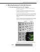
ENC10/12, ENC12/14, ENC14/16, ENC16/18 3. Mounting Equipment Inside the Enclosure 3.1 Enclosures with One or Two 1.5” Conduits 1. If installing the optional Door Switch Indicator, follow the procedure described in Appendix A. 2. If installing the 25458 DIN-Rail Terminal Kit, follow the procedure described in Appendix B. The 25458 kit facilitates wiring when many wires need to be connected to one terminal. 3.
ENC10/12, ENC12/14, ENC14/16, ENC16/18 NOTE 4. If desired, insert the 25745 PVC coupling to reduce the conduit’s diameter to 0.5”. Route the sensor leads through the enclosure conduit to the datalogger and peripheral terminal strips. 5. Connect sensors and peripherals to the datalogger as described in the sensor and peripheral manuals. 6. Secure sensor and peripheral leads to the side of the enclosure using 8” cable ties and cable tie tabs (see Figure 3-2).
ENC10/12, ENC12/14, ENC14/16, ENC16/18 FIGURE 3-2.
ENC10/12, ENC12/14, ENC14/16, ENC16/18 FIGURE 3-3. An ENC12/14 with one 1.5” conduit houses a CR1000 datalogger and BP24 power supply. Door not shown. 3.2 Enclosures with Individual Compression Fittings 1. If installing the optional Door Switch Indicator, follow the procedure described in Appendix A. 2. Use the #6 screws and plastic grommets (Figure 3-1A) to mount additional peripherals to the enclosure backplate (Figure 3-1B).
ENC10/12, ENC12/14, ENC14/16, ENC16/18 NOTE 3. Route each sensor and peripheral lead through a unique compression fitting (see Figure 3-4). 4. Connect sensors and peripherals to the datalogger as described in the sensor and peripheral manuals. 5. Secure sensor and peripheral leads to the side of the enclosure using 8” cable ties and cable tie tabs (see Figure 3-2). The adhesive of the cable tie tab may not stick during extremely cold temperatures or extremely high humidity.
ENC10/12, ENC12/14, ENC14/16, ENC16/18 4” Cable Tie Secures Cable to CR1000 Compression Fittings FIGURE 3-5. This ENC16/18 enclosure with the “-ES” option houses the equipment commonly used in a GOES satellite system. 4. Attachment to an Instrument Mount 4.1 Tripod Mast The “-MM” mount option is intended for mounting our enclosures to the mast of any of our tripods.
ENC10/12, ENC12/14, ENC14/16, ENC16/18 FIGURE 4-1. An enclosure with the “-MM” mounting option attaches to a tripod mast via u-bolts. FIGURE 4-2. This exploded view shows the components of a “-MM” bracket.
ENC10/12, ENC12/14, ENC14/16, ENC16/18 FIGURE 4-3. An enclosure attached to a tripod mast. 4.2 UT10 10 ft Tower The “-TM” option is used to attach our enclosures to a UT10 tower. An enclosure ordered with the “-TM” option will be shipped with a three-piece bracket mounted to the top of the enclosure and an identical three-piece bracket mounted to the bottom of the enclosure.
ENC10/12, ENC12/14, ENC14/16, ENC16/18 same three-piece brackets as the "-MM" option, except the pieces are rearranged so that the flanges are on the side of the bracket instead of in the middle. The distance between the centers of each flange needs to be 17” (see Figures 4-4, 4-5, and 4-6). NOTE Enclosures with the "-TM" option are shipped configured for the UT10 tower. Steps 1 through 3 of the following procedure are for configuring the bracket for attachment to a UT20 or UT30 tower.
ENC10/12, ENC12/14, ENC14/16, ENC16/18 The default configuration is for attaching to a UT10 tower (i.e., D = 10.25”). To attach to a UT20 or UT30 tower, move the flange sections of the bracket so that D = 17”. Flange Section Flange Section FIGURE 4-5. This exploded view shows the components of a “-TM” bracket option. FIGURE 4-6. An enclosure attached to two tower legs.
ENC10/12, ENC12/14, ENC14/16, ENC16/18 4.4 Tripod Leg Base The “-LM” mount option is intended for attaching an enclosure to the leg base of a CM106, CM106K, CM110, CM115, or CM120 tripod. NOTE The ENC16/18 can be mounted to the leg base of a CM106 or CM106K only. An enclosure ordered with this option will be shipped with a bracket attached to each side of the enclosure and a u-bolt bracket. A 19124 bracket must also be attached to some tripods (see Figure 4-7).
ENC10/12, ENC12/14, ENC14/16, ENC16/18 Flange FIGURE 4-7. The 19124 bracket attached to a CM110 tripod. Notch FIGURE 4-8. An ENC14/16 enclosure with a “-LM” Bracket.
ENC10/12, ENC12/14, ENC14/16, ENC16/18 FIGURE 4-9. The u-bolt bracket. FIGURE 4-10. An enclosure attached to the leg base of a CM110 tripod.
ENC10/12, ENC12/14, ENC14/16, ENC16/18 4.4.1 Mounting More Than One Enclosure on a Tripod Leg (CM110, CM115, CM120) It is possible to mount two enclosures back-to-back on the CM110, CM115, and CM120 tripods. If the enclosures are different sizes, mount the smaller enclosure first, followed by the larger enclosure. If the enclosures are the same size, use two 5/16-18 x 3.50” bolts in place of u-bolts to anchor the two enclosures together. FIGURE 4-11. Mounting Two Enclosures on a Single Tripod Leg 4.
ENC10/12, ENC12/14, ENC14/16, ENC16/18 Bracket Enclosure Bolt Washer LockNut FIGURE 4-12. Attaching the Pole Mount Bracket 2. Feed a metal band through the openings in each bracket as shown in Figure 4-13. Use the closest set of holes for smaller poles and the farthest set of holes for larger poles. Mounting Bracket Band FIGURE 4-13. Inserting the Metal Band 3. Position the enclosure on the north side of the tower. 4. Place the enclosure at the desired height.
ENC10/12, ENC12/14, ENC14/16, ENC16/18 5. Insert the tab on the end of the Screw Threads (Figure 4-14) into the hole at one end of the upper strap. Mounting Pole Enclosure Band Screw Threads Screw Clamp FIGURE 4-14. Securing the Enclosure to a Pole 6. Pull the strap tight around the pole to determine which hole to insert the Screw Clamp at the other end of the strap. Insert the clamp into this hole. 7. Use metal shears to remove any excess strap, leaving a small amount for adjustments. 8.
ENC10/12, ENC12/14, ENC14/16, ENC16/18 5. When to Replace Desiccant The humidity indicator card or optional CS210 Humidity Sensor indicate when the desiccant needs to be replaced. CAUTION Campbell Scientific strongly suggests replacing desiccant instead of reactivating old desiccant. Improper reactivation can cause the desiccant packets to explode. If you are determined to reactivate old desiccant packets, follow one of the procedures provided in Appendix C. 5.
ENC10/12, ENC12/14, ENC14/16, ENC16/18 CAUTION 3. Use a fine grain sandpaper to gently sand the enclosure surface; if the surface of the enclosure is sufficiently rough, this step may be skipped. 4. Spray with clear acrylic paint. Properly ventilate the area while using solvent and paint. Wear safety goggles, mask, and gloves while sanding. 6.2 Primer and White Paint CAUTION 20 1. Use a rag and possibly a solvent to clean the outside of the enclosure.
Appendix A. Door Switch A.1 Installation Procedure A.1.1 Newer ENC16/18 (see Figure A.1-1) No Offset FIGURE A.1-1. This procedure is for ENC16/18 enclosures that do NOT have an offset near the edge of the enclosure door. Follow the procedure provided in section A.1.2 if your ENC16/18 has an offset. 1. Mark locations to drill on the upper right side of the enclosure as shown in Figure A.1-2. FIGURE A.1-2. The proper placement of the screw holes are shown in a close-up (left photo) and distant view.
Appendix A. Door Switch 2. Using a #22 (.157) drill, drill pilot hole from inside of case and final hole from the outside so that enclosure finish does not crack. 3. Attach switch to enclosure case using #6-32 screws and nuts (see Figure A.1-3). FIGURE A.1-3. Switch installed in the enclosure case. 4. Attach actuator to door using #6-32 screws and nuts (see Figure A.1-4). FIGURE A.1-4. Actuator installed in the enclosure door.
Appendix A. Door Switch A.1.2 ENC14/16 and Older ENC16/18 (see Figure A.1-5) Offset Offset FIGURE A.1-5. Customers with ENC16/18 enclosures should use this procedure if their enclosure has an offset near the edge of the enclosure door as shown in the photograph. 1. Mark locations to drill on the upper right side of the enclosure as shown in Figure A.1-6. 2. Using a #22 (.157) drill, drill pilot hole from inside of case and final hole from outside of case so that enclosure finish does not crack.
Appendix A. Door Switch 3. Assemble the switch as shown in Figures A.1-7 and A.1-8. FIGURE A.1-7. Place the #18431 switch on the #18176 bracket with the holes of switch located over the bracket tabs. FIGURE A.1-8. Secure the #18431 switch with the #18177 back bracket.
Appendix A. Door Switch 4. Mount the switch to the enclosure case using two #17909 screws and two #8548 nuts (see Figure A.1-9). FIGURE A.1-9. The switch mounts inside the enclosure case. Line up the switch so that the screws fit in the holes previously drilled. 5. As shown in Figure A.1-10, assemble the actuator and mount it in the enclosure door. FIGURE A.1-10. The actuator mounts inside the enclosure lid. Line up the actuator so that the screws fit in the holes previously drilled.
Appendix A. Door Switch A.1.3 ENC12/14 and ENC10/12 1. Mark locations to drill on the upper right side of the enclosure as shown in Figure A.1-11. 2. Using a #22 (.157) drill, drill pilot hole from inside of case and final hole from outside of case so that enclosure finish does not crack. FIGURE A.1-11. The proper placement of the screw holes are shown. Ensure both brackets are aligned with each other. 3. Assemble the mounting bracket as shown in Figure A.1-12. FIGURE A.1-12.
Appendix A. Door Switch 4. Place PN 18175 actuator in bracket with holes of actuator located over bracket tabs. Slide inner bracket in the direction shown in Figure A.1-13 to secure in place. FIGURE A.1-13. Securing the actuator 5. Attach actuator to door using two #17909 screws and two #8548 nuts (see Figure A.1-14). FIGURE A.1-14. The actuator attached to the enclosure door.
Appendix A. Door Switch 6. Attach PN 18431 switch to enclosure case using PN 18178 mount with two #17909 screws and two #8548 nuts (see Figure A.1-15). FIGURE A.1-15. The switch attached to the enclosure case. A.2 Example Programs A.2.1 CRBasic 'Program name: DOOR SWITCH CR1000.
Appendix A.
Appendix A.
Appendix A. Door Switch ; Reset door status after output interval 13: If time is (P92) 1: 0 Minutes (Seconds --) into a 2: 5 Interval (same units as above) 3: 30 Then Do 14: Z=F x 10^n (P30) 1: 0.
Appendix A.
Appendix B. 25458 DIN-Rail Terminal Kit B.1 Introduction The 25458 kit can facilitate wiring when many wires need to be connected to one terminal. The kit contains one 15906 5-inch DIN-Rail Mounting Bracket, two 505 screws, two 6044 grommets, and two 15908 DIN-Rail Stoppers. A complete configuration will also include #15920 Terminal Strips, #15907 End Plates, and #15909 Jumpers. The stoppers, terminal strips, and end plates are mounted onto the DIN Rail bracket.
Appendix B. 25458 DIN-Rail Terminal Kit FIGURE B-2. 15920 Terminal Strip Installation FIGURE B-3.
Appendix B. 25458 DIN-Rail Terminal Kit 2. Insert the 15909 Jumpers in the terminal strips as shown in Figure 4. FIGURE B-4. 15909 Jumper Installation 3. Mount the DIN Rail bracket onto the enclosure backplate using two 505 screws and two 6044 grommets (see Figure 5). FIGURE B-5.
Appendix B. 25458 DIN-Rail Terminal Kit 4. Connect the wires to the terminals (see Figures 6 and 7). The 8125 flatbladed screwdriver is used to open the terminals’ guillotines for wire entry. FIGURE B-6. An Installed and Wired 25458 DIN Rail Terminal Kit FIGURE B-7. The 25458 DIN Rail Terminal Kit facilitates wiring of multiple HMP45C sensors.
Appendix C. Reusing Desiccant Because desiccant is inexpensive, most users replace the desiccant instead of reactivating saturated desiccant. However some customers wish to reactivate saturated desiccant. To do this, care must be taken to prevent the desiccant packets from exploding during the reactivation process. This problem is caused by using too rapid of a heating process.
Appendix C.
Campbell Scientific Companies Campbell Scientific, Inc. (CSI) 815 West 1800 North Logan, Utah 84321 UNITED STATES www.campbellsci.com • info@campbellsci.com Campbell Scientific Africa Pty. Ltd. (CSAf) PO Box 2450 Somerset West 7129 SOUTH AFRICA www.csafrica.co.za • cleroux@csafrica.co.za Campbell Scientific Australia Pty. Ltd. (CSA) PO Box 444 Thuringowa Central QLD 4812 AUSTRALIA www.campbellsci.com.au • info@campbellsci.com.au Campbell Scientific do Brazil Ltda.