
Specifications

ENC10/12, ENC12/14, ENC14/16, ENC16/18
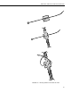
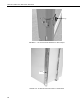
3. Route each sensor and peripheral lead through a unique compression
fitting (see Figure 3-4).
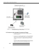
4. Connect sensors and peripherals to the datalogger as described in the
sensor and peripheral manuals.
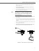
5. Secure sensor and peripheral leads to the side of the enclosure using 8”
cable ties and cable tie tabs (see Figure 3-2).
The adhesive of the cable tie tab may not stick during extremely
cold temperatures or extremely high humidity. In these
situations, fasten the cable tie tab to the backplate using a #6
screw and grommet or run the cable tie through two of the
enclosure backplate holes.
NOTE
6. Strain relief the sensor leads to the datalogger’s strain relief flanges with
the 4” cable ties.
7. Place two of the desiccant packs from the Enclosure Supply Kit inside of
the enclosure. Reseal the other two inside the plastic bag to use later (see
Section 5).
8. Remove the backing from the humidity indicator card and attach the card
to the right side of the enclosure.
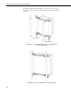
9. Rotate each compression fitting so that the fitting clamps tightly against
the sensor cable to provide a water-tight seal (see Figure 3-4).
1
2
3
FIGURE 3-4. Cable Inserted into Compression Fitting
7