
Specifications

Appendix A. Door Switch
A.1 Installation Procedure
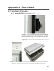
A.1.1 Newer ENC16/18 (see Figure A.1-1)
N
o Offse
t
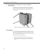
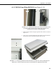
FIGURE A.1-1. This procedure is for ENC16/18 enclosures that do
NOT have an offset near the edge of the enclosure door. Follow the
procedure provided in section A.1.2 if your ENC16/18 has an offset.
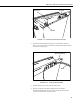
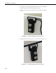
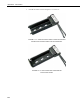
1. Mark locations to drill on the upper right side of the enclosure as shown in
Figure A.1-2.
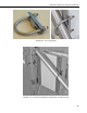
FIGURE A.1-2. The proper placement of the screw holes are shown in a close-up (left photo) and
distant view. Ensure that the screw holes for both brackets are aligned with each other.
A-1