Instruction Manual Model 8025 Series Datalogger (Micro-800) Multi-Channel Datalogger No part of this instruction manual may be reproduced, by any means, without the written consent of Geokon, Inc. The information contained herein is believed to be accurate and reliable. However, Geokon, Inc. assumes no responsibility for errors, omissions or misinterpretation. The information herein is subject to change without notification. Copyright © 2013 by Geokon, Inc.
Warranty Statement Geokon, Inc. warrants its products to be free of defects in materials and workmanship, under normal use and service for a period of 13 months from date of purchase. If the unit should malfunction, it must be returned to the factory for evaluation, freight prepaid. Upon examination by Geokon, if the unit is found to be defective, it will be repaired or replaced at no charge.
Table of Contents Overview .............................................................. 1. Hardware …………………………………….. 1.1 Installation ………………………….. 1.2 Power ……………………………….. 1.3 Earth Ground ……………………….. 1.4 Gages ……………………………….. 1.5 Communications ……...…………….. 2. Software ………………………………........... 3. Battery Maintenance …………………………. 3.1 AC Power …………………………... 3.2 Solar Power ………………………… 3.3 External Battery …………………….. 3.4 Battery Replacement ………………... 3.5 Fuses ………………………………... 4.
Appendix Appendix A - Specifications A.1 CR800 Measurement and Control Module ….....……... 7 A.1.1 Analog Inputs ………………………………………. 7 A.1.2 Excitation Outputs ………………………….............. 7 A.1.3 Pulse Inputs …………………………………………. 7 A.1.4 Control Ports ……………………………………...… 8 A.1.5 Model 8032 Multiplexer ……………………………. 8 A.1.6 AVW200 Vibrating Wire Interface ………………… 8 Appendix B – Ship List B.1 Hardware ……………………………………………… 8 Appendix C – Data Storage C.1 Input Locations ……………………………………….. 9 C.
1 OVERVIEW The MICRO-800 Datalogger is designed to support the reading of a large number of Geokon Vibrating Wire Instruments for various unattended data collection applications through the use of an internal Geokon Model 8032 Multiplexer. Weatherproof packaging allows the unit to be installed in field environments where inhospitable conditions prevail. The Nema 4X enclosure also has a provision for locking to limit access to responsible field personnel.
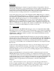
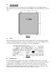
2 1.1 INSTALLATION The recommended method of installation involves attaching the enclosure (MICRO-800) to a fixed structure, such as a wall, in an upright position (Figure 1). Mounting dimensions shown in inches. Figure 1 1.2 Power After the Datalogger is installed the charger can be plugged into the AC mains and the On/Off switch S1 on the Charge Regulation circuit board switched to the “On” position (Figure 2). It is recommended that the charger be left plugged in at all times (Section 3.1).
3 1.4 Gages At this time the vibrating wire sensors can be connected to the multiplexer. Please refer to Appendix F for the appropriate connection description. 1.5 Communications Standard communications with the Datalogger is established by connecting the supplied serial cable to the RS-232 port (Figure 3) and the COM port on a computer, or a USB port on the computer by using the provided USB to Serial converter cable. Figure 3 2.
4 3. BATTERY MAINTENANCE 3.1 AC Power The MICRO-800 is supplied with an external AC to DC power supply for maintaining the charge of the battery and providing power to the Datalogger and peripherals. It is imperative that the power supply remain connected to the Datalogger as the battery installed in the Datalogger is only provided as a temporary source of power should the power supply be disconnected or mains power interrupted.
5 4. TROUBLESHOOTING This section will NOT attempt to cover all possible problems that could be encountered in the course of Datalogger operations. Consult the factory if other problems arise or remain unresolved. • Cannot communicate with the Datalogger. Suggestions: 1. The wrong communication cables are being used or the cables in use are defective. Consult Appendix D.1.2 to verify cable pinout. Consult the factory for interfacing information. 2. The internal battery could be dead.
6 • The Datalogger will not operate on external power. Suggestions: 1. The external voltage supply is below operating limits. If the external source is a battery, charge it. If it’s a power supply, check the output with a voltmeter. 2. The external power or battery fuse is blown (Section 3.5). • Loss of CR800 program and/or data. Suggestions: 1. The system has experienced a voltage dropout or surge which disrupted operations. 2. The surge originated as a result of lightning.
7 APPENDIX A - SPECIFICATIONS A.1 CR800 Measurement and Control Module Power requirements: 9.6 to 16 VDC Analog measurement current drain: 27.6 mA Processing current drain: 16.2 mA Quiescent current drain: .
8 A.1.4 Control Ports Configuration: 4 digital I/O ports Input/output resistance: 100kΩ/330Ω, respectively Input “high” level: 3.8 V to 5.3 V Input “low” level: -0.3 V to 1.2 V Output “high” level: 5 V ±0.1 V Output “low” level: <0.1 V A.1.5 Model 8032 Multiplexer (See the Appendix F complete specifications) A.1.6 AVW200 Vibrating Wire Interface (See AVW200 Manual for complete specifications) Power requirements: 9.6-16 VDC Vibrating Wire measurement current: 25 mA Quiescent current: .
9 APPENDIX C – DATA STORAGE C.
10 C.2 Data Storage Total Arrays of Data that can be stored per 16 Channel Multiplexer. Each array contains all Data stored at each read interval. 1 Multiplexer Array Storage 2 Multiplexer Array Storage 3 Multiplexer Array Storage 4 Multiplexer Array Storage 5 Multiplexer Array Storage 6 Multiplexer Array Storage C.
11 APPENDIX D – SYSTEM WIRING D.
12 D.1.
13 D.1.4 Charger Wiring Pin A B C D.2 Description Charger + (14-22 VDC Input) Ground Battery + (12 VDC Output) Wire Color Grey Blue Violet Cables D.2.1 AC Charger (110VAC/220VAC) Pin A B Description Charger + (14-22 VDC Input) Ground Condor - Wire Color Black with White Stripe Black D.2.2 External Power Cable Pin A B C D.
14 D.
15 APPENDIX E –LOGGERNET QUICKSTART GUIDE E.1 Overview Campbell Scientific’s LoggerNet Software is used to communicate with the Datalogger, program user specific settings and collect Data stored in the Datalogger memory. LoggerNet is designed to be used with Geokon Micro-1000 and Micro-800 Dataloggers reading Vibrating Wire and MEMS tilt sensors; other configurations and sensor outputs are available upon request.
16 By default, the EZ View of the Setup Screen is displayed. To change the viewing method press the “Std View” icon at the top right of the Setup Screen. This Quick Start will show the “Std View” of the Setup Screen. To add a communication port, press “Add Root” button. Each Datalogger will communicate via RS232. Select connection type “ComPort”, “PakBusPort (Other Loggers)”, “CR1000” or “CR800Series” and press “Close”.
17 Select “ComPort” under the “Network Map”, select the communications port to connect to the Datalogger in “ComPort Connection”. CONDITIONAL NOTE: IT MAY BE NECESSARY TO PRESS “COMMUNICATIONS ENABLED ” TO OPEN THE COMMUNICATIONS PORT. COM NUMBERS VARY WITH COMPUTER , USB DEVICES AND SERIAL ADAPTERS. REFER TO THE COMPUTER DEVICE MANAGER IF UNSURE OF WHICH COM NUMBER TO USE . Select “PakBusPort” under the “Network Map”, in “Maximum Baud Rate” for direct connection to the Datalogger select “115200”.
18 E.2.3 Connecting to the Datalogger With the LoggerNet Launch Menu open, hover over “Main” and press “Connect”. Select the Datalogger to communicate with under “Stations” and press the “Connect” button.
19 E.3 Modifying the Datalogger Program Navigate to the Include(.DLD) file on the end user’s computer C:\Campbellsci\CRBasicEditor. Optional changes to Scan Interval, Zero Readings, Gage Factors and Alias names can be made by opening the Include(.DLD) file with Notepad. Each Datalogger configuration has a unique Include(.DLD) file. WARNING: ONLY CHANGE VALUES AFTER THE “=” SIGN. E.3.
20 Temperature Zero Readings & Thermal Factors NOTE: TEMPERATURE ZERO AND THERMAL FACTORS ARE USED FOR TEMPERATURE CORRECTION. TEMPERATURE CORRECTION MAY BE USED TO COMPENSATE FOR CHANGES IN A GAGE’S READINGS DUE TO TEMPERATURE CHANGE. TEMPERATURE EFFECT ON READINGS VARIES ON DIFFERENT MODELS OF GAGES AND TEMPERATURE CORRECTION IS OFTEN NOT REQUIRED. DEPENDING ON THE GAGE MODEL TEMPERATURE CORRECTION MAY NOT BE AVAILABLE AND SOME GAGE MODELS REQUIRE A DIFFERENT FORMULA TO COMPENSATE.
21 Output Labels Default Alias names correspond with the Direct or Multiplexer channel for each specific gage. Alias names get displayed in the Header of the Data file, and can be modified by the user. WARNINGS: ALIAS NAMES CANNOT BE MORE THAN 35 CHARACTERS LONG AND MUST ONLY CONTAIN ALPHANUMERIC VALUES AND UNDERSCORES (NO SPACES OR SYMBOLS). SAVE THE INCLUDE FILE IF MODIFIED. E.3.2 Uploading Files The Include.DLD file must be saved when modified. After modification, the Include.
22 Select DLD file type to make the Include(.DLD) file visible in C:\Campbellsci\CRBasicEditor. Uncheck “Run Now”, the Include(.DLD) file cannot run the Datalogger.
23 Sending the Main program file (.CR8/CR1) To send the Main(.CR8/CR1) CRBasic Program from the “Connect Screen” press “Send” and select the Main(.CR8/CR1) program file in C:\Campbellsci\CRBasicEditor. NOTE: EACH DATALOGGER HAS A UNIQUE INCLUDE(.DLD) AND MAIN(.CR8/CR1) FILE When sending the Main(.CR8/CR1) program file through the “Connect Screen” the program runs automatically. E.4 Data Handling E.4.
24 Select the Datalogger “CR1000”/“CR8000Series”, “Data Files” tab then select “Table1”. Dataloggers can be renamed by pressing “Rename” button. Renaming the Datalogger affects the name of the Data file. “Output File Name” option allows changing the file name, where to collect and store the Data file. “File Output Option” determines whether new Data collected is appended into one file, overwrites old Data, or creates a new file every time Data is collected.
25 Once the program is running, most current readings can be viewed under “Table1” of the “Table Monitor” and “Num Display”. “Graphs” can also be used to view live and historical Data. CONDITIONAL NOTE: IT MAY BE NECESSARY TO START MONITORING BY PRESSING “START”. E.4.3 Collecting Data Pressing “Collect Now” collects and stores Data on the computer. After collecting Data a “Data Collection Results” screen will open. PLEASE SEE LOGGERNET MANUAL FOR MORE SPECIFIC DETAILS REGARDING USE OF THE SOFTWARE.
26 APPENDIX F –8032 MULTIPLEXER Manual The following Appendix includes excerpts from the Model 8032 Multiplexer manual that apply to the Micro-800. A complete version of the Model 8032 Multiplexer Manual can be found at WWW.GEOKON.COM. THEORY OF OPERATION The Model 8032 Multiplexer expands the number of channels that can be read by the MICRO-800 Datalogger or MICRO-1000 Datalogger.
27 Supported switching arrangements: Multiplexer/Terminal Board 31H 32H 32L 31L CR800/CR1000 Microcontroller 12V GROUND RESET CLOCK S16 12V GROUND RESET CLOCK Sensor #16 Sensor Shield Relay Control COM HI 1 COM LO 1 COM HI 2 COM LO 2 AG 1H 2H 2L 1L S1 Sensor #1 Sensor Shield Figure 1 - 16 Channel Switching Block Diagram The 16 channel 4 wire switching configuration is typically used to multiplex 4 wire sensors such as resistance strain gage load cells.
28 Multiplexer/Terminal Board 32H Sensor #32 CR800/CR1000 32L S16 Microcontroller 12V GROUND RESET CLOCK Sensor Shield 12V GROUND Relay Control RESET CLOCK COM HI COM LO AG 1H Sensor #1 1L S1 Sensor Shield Figure 2 - 32 Channel Switching Block Diagram The 32 channel 2 wire switching configuration is typically used to multiplex 2 wire sensors such as a vibrating wire pressure transducers, thermistors or thermocouples. The multiplexer is powered by a nominal 12 VDC supply.
29 Figure 4 illustrates the DIP switch SW2 for switching between a GK-403 or Datalogger application. “DATALOGGER”” is the default SW2 position: SW2 GK-403 DATALOGGER Figure 4 – GK-403/DATALOGGER Selection MICRO-1000 / 800 (CR1000 / CR800) Mode of Operation The MICRO-800 and MICRO-1000 (which respectively utilize a CR800 and CR1000 controller, manufactured by Campbell Scientific, Inc. of Logan, Utah) mode of operation uses two control lines to operate the multiplexer.
30 T1 T2 T3 Reset Pulse 1 Clock No Channel Selected Pulse 2 Channel 1 Selected Channel 2 Selected Pulse 32 Channel 32 Selected No Channel Selected Timing: T1 = 50 mSec (min) T2 = 2 mSec (min) T3 = 2 mSec (min) Figure 8 - 32 Channel MICRO-800/MICRO-1000 Channel Selection Timing
31 WIRING Actual gage connections to the terminal board will vary depending on the instrument type and cable used. Note the following tables to get the general idea.
32 Figure 10 depicts the terminal board to which gage connections are made. If the terminal board is equipped with manual switches, connectors J1 and J2 will have ribbon cables that are connected to the switch boards. Terminal Blocks T1/2 to T31/32 are for the gage connections.
33 TROUBLESHOOTING Below are some commonly experienced problems along with possible remedial action. Contact the factory if any problem remains unresolved or additional help is required. A particular channel on the multiplexer appears to be malfunctioning. • Check sensor connections on the terminal board. Clean if corrosion exists. • Try moving the sensor wired to the suspect channel to another channel to verify the malfunctioning of the channel (as opposed to the sensor). No channels are working.
34 SPECIFICATIONS A.1 General Power Requirements: 10-16 VDC (unregulated) Quiescent Current (MICRO-800/MICRO-1000 mode): 80 µA (16CH mode) 130µA (32CH mode) Quiescent Current (GK-403 mode): 12 mA Channel Activated Current: 30 mA Control Line Input Impedance: 100 kΩ (CLOCK), 100 kΩ (RESET) Control Line Input Levels: TTL or RS-232 (±9 VDC) Transient Protection: 16 VDC Transzorbs Operating Temperature: −40 to +60° C A.2 Relays Type: NAIS TXS2SA-4.5V DPDT non-latching Power: 11.1 mA @ 5VDC (55.
35 A.5 Inductor Rated Current: 4A Inductance: 10µH (±20%) D.C.R.: 25mΩ MAX (at 20°C) A.6 Transient Voltage Suppressor (Transorb) Rated Power: 1500W Peak forward Surge Current: 200A Reverse Standoff Voltage: 16.0V A.7 Transducer Connection Maximum Operating Voltage Levels: Common-mode Voltage/Earth Ground: 16V(max) Differential-mode Voltage (Channel # ‘H’ – Channel # ‘L’): 16V(max) A.
36 CONNECTOR AND CABLE WIRING J4 1 2 3 4 5 6 7 8 9 10 Inside Color Brown Red Orange Yellow Green Blue Purple Grey 10 Pin Bendix A B C D K F G H White J E Description COM HI 1 COM LO 1 COM HI 2 (16 channel) COM LO 2 (16 channel) Analog Ground +12 Volt Power Power Ground RESET (DATALOGGER) SENSE (GK-403) CLOCK No Connection 8032-5 (TAN) Cable Wire Color White White's Black Red Red's Black Shield Drain Wires – all pairs plus overall Yellow Yellow's Black Green Green's Black Blue & Blue’s Black (unused)
37 DAISYCHAIN OPERATION Up to (8) 8032’s may be ”daisychained” together using a common RESET and CLOCK control line. This may be advantageous in situations where either there are not enough control ports available on the Micro-800/MICRO-1000 datalogger for the number of multiplexers desired, or to reduce the number of cables required to implement a large multi-channel system.
38 Micro-800/1000 Datalogger C7 C8 Reset Clock Reset IN Clock J H VW Gages 1-32 VW Gages 33-64 VW Gages 65-96 H OUT Reset IN H OUT Reset IN SW1 SETTING: 2 3 4 OFF OFF OFF Clock J H H J Multiplexer #1 MUX1 J Multiplexer #2 MUX2 SW1 SETTING: 2 3 4 OFF OFF ON Clock J Multiplexer #3 MUX3 SW1 SETTING: 2 3 4 OFF ON OFF Figure D.
39 MAXIMUM 8032-5 (TAN CABLE) CABLE LENGTHS The 8032 Multiplexer is a low power device, that when combined with a Micro-800 or Micro1000 Datalogger can be physically located at a considerable distance from that Datalogger. Still, there are limits to the maximum distance – mostly due to the voltage dropped by the 8032-5 MUX cable over its length.