INSTRUCTION MANUAL CC5MPX Series Digital Network Camera .BZ 2015 Copyright © 2015 Campbell Scientific (Canada) Corp.
Table of Contents PDF viewers: These page numbers refer to the printed version of this document. Use the PDF reader bookmarks tab for links to specific sections. 1. Introduction ................................................................ 1 2. Specifications............................................................. 2 3. Getting Started ........................................................... 3 3.1 3.2 3.3 3.4 Factory Setup .........................................................................
Table of Contents 7.5 7.6 7.7 7.8 7.9 7.4.3 Site Name ................................................................................... 31 7.4.4 Users and Security...................................................................... 31 7.4.5 Digital I/O Settings .................................................................... 32 7.4.5.1 External Trigger Input Settings ....................................... 33 7.4.5.2 Light Power Control Settings .......................................... 33 7.4.
12. Device Configuration Utility .................................... 72 13. Image Quality ........................................................... 74 13.1 Night Time Images............................................................................. 74 14. Lens .......................................................................... 74 14.1 Camera Lens and Field of View......................................................... 76 14.2 Focus and Zoom Adjustment ........................................
Table of Contents Appendix A. CC5MPX Series Cameras and Accessories .......................................................... A-1 A.1 A.2 A.3 A.4 A.5 A.6 A.7 A.8 A.9 CC5MPXWD .................................................................................. A-1 CC5MPX with Zoom Lens.............................................................. A-1 CC5MPXFE .................................................................................... A-1 Window Defroster ............................................
Figure 7-24 Example of Multiple Page Viewing ........................................... 39 Figure 7-25 Video Settings Page ................................................................... 39 Figure 7-26 Video Banner Inside Top with Timestamp and Text ................. 40 Figure 7-27 Image Capture Page ................................................................... 42 Figure 7-28 Power Modes..............................................................................
Table of Contents Tables Table 3-1 CC5MPX Default Configuration .................................................... 3 Table 4-1 Power & I/O Cable Color Connections ........................................ 10 Table 4-2 Power & I/O Cable Wire Usage ................................................... 11 Table 5-1 Setup Button LED Indicator ......................................................... 15 Table 7-1 Network Settings ..........................................................................
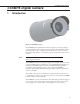
CC5MPX Digital Camera CC5MPX Digital Camera 1. Introduction Figure 1-1 CC5MPX Camera The CC5PMX Series digital network cameras are designed to meet the stringent operational requirements necessary for remote battery powered installations while producing images of up to 5 megapixels. Both cameras can operate over a wide temperature range and have several advanced power saving modes to suit a variety of needs.
CC5MPX Digital Camera 2. Specifications Power Supply Operating: 9-30 VDC 250 mA Maximum (Camera only) 9-16 VDC 1.0 A Max @ 12 VDC (Camera w/ Defroster Option)* Quiescent: Note 1 mA Maximum (Off power mode) *Warning: The CC5MPX is specified to operate on a 9-30 VDC supply input range. When the window defroster is installed, the 30 VDC maximum must be reduced to 16 VDC. Operating the CC5MPX with window defroster at voltages greater than 16 VDC can cause damage to the CC5MPX.
CC5MPX Digital Camera Communication Switched Power Output Maximum Output Current: 750 mA RS-232 and RS 485 Max. BAUD rate: 115.2 KBAUD Note The recommened maximum cable length at this BAUD rate is 15 meters. The use of the 57.6 KBAUD rate has a recommended maximum cable length of 30 meters. Memory Card Interface Type: Secure Digital (SD) File System: FAT32 File Type: JPEG (image), AVI (video) Size: Verified up to 16 GB Dimensions Length: 220 mm (8.7”), 229 mm (9.0”) w/ zoom lens Width: 93 mm (3.
CC5MPX Digital Camera There are two different ways to set up the parameters in the CC5MPX. The Ethernet network interface can be used with a web browser of the RS-232 serial lines can be used with Campbell Scientifics’ Device Configuration utility. The use of RS-232 serial lines will require the use of the DB9 terminal block adapter in order to connect to a PC (Section 4, Table 4-1). When power is first applied to the camera the LED will turn on and remain steadily on for about 90 seconds.
CC5MPX Digital Camera 3.4.2 Static IP Address Setup If your computer is not set to use DHCP to obtain an IP address automatically, you will need to follow the procedure outlined in this section to access the camera’s webpage. It may be beneficial to speak with someone in your IT department if you are not familiar with configuring devices for operation on a network. The default static IP address for the camera is 192.168.1.90.
CC5MPX Digital Camera Under Connections on the right-hand-side, click Local Area Connection, then select Properties. Figure 3-2 Local Area Connection Properties Click on Internet Protocol Version 4 (TCP/IPv4), then select Properties.
CC5MPX Digital Camera You should record existing settings that are used on the computer to restore the connection once the CC5MPX setup is complete. In Figure 3-3, the computer is set to obtain the IP address automatically. Click Use the following IP address and enter to following values: x IP address: 192.168.1.91 x Subnet mask: 255.255.255.0 x Default gateway: 192.168.1.1 Figure 3-4 IP Address Configuration Click OK to accept. This may prompt a Microsoft TCP/IP Warning pop-up.
CC5MPX Digital Camera Figure 3-5 Web Interface Live Video Home Page If you select a video format to display from the Video Display Size dropdown box, you should be prompted to install or allow an ActiveX control. By default, your browser may be configured to block pop-ups. You will need to enable the pop-up for the camera. Now that a connection has been established, please see Section 7.3 for further instructions on how to change the camera’s network settings.
CC5MPX Digital Camera Once the appropriate selections are made, select the connect button. Figure 3-6 CC5MPX shown in Device Configuration Utility The camera has a large number of variable information so it may take about 30 secs for this process to be complete. Once the settings are loaded, clicking the tabs located near the top of the page will allow navigation to the various settings.
CC5MPX Digital Camera 4. Cables/Wiring 4.1 Power & I/O Cable Connections The wiring for the Power & I/O Cable connector assemble is as shown in Table 41. The wires can be terminated directly on the control ports of a compatible datalogger.
CC5MPX Digital Camera Refer to Table 4-2 to help determine which wires will need to be connected for your camera application. Table 4-2 Power & I/O Cable Wire Usage Wire Color Function Connection Required When not Used Black Power Ground Always Red Input Power Always Green RS-232 TX (output) OR RS-484A The Green wire only needs to be connected when RS-232 or RS-485 communications are used for PakBus or the Device Configuration Utility.
CC5MPX Digital Camera 4.2 Power & I/O Cable Details The Power & I/O cable that is used for the CC5MPX camera has an outdoor environmentally rated screw type connector on one end and discrete wire pigtails on the other end that allow for flexible termination. When making the cable connection to the camera the notch positions should always be lined up and care should be taken to not cross the connector. For information about the cable options available, see Appendix A.
CC5MPX Digital Camera 4.3 Ethernet Cables The Ethernet connection is used to configure the camera settings as well as for targeting and focusing the camera. The Ethernet port of the CC5MPX is auto MDIX; therefore, an Ethernet crossover cable is not required when connecting the camera to other devices. A standard CAT5 (or better) Ethernet cable with RJ45 connectors can be used to interface to the camera in indoor conditions or for temporary connection outdoors when conditions permet.
CC5MPX Digital Camera 5.1 Ethernet RJ45 Connection The RJ45 connector on the camera is meant to interface the CC5MPX with either a network router, cellular modem, or directly to a laptop. If a permanent Ethernet connection is not required for an outdoor environment, then the protective cap must be securely attached to the Ethernet connector to provide an environmental seal.
CC5MPX Digital Camera 5.3.1 Status LED The Status LED located in the center of the button provides some useful diagnostic information about the camera. Table 5-1 describes the LED behavior.
CC5MPX Digital Camera 5.4 SD Memory Card The camera is internally equipped to use an SD memory card. An extended temperature memory card is available as an option for the CC5MPX. If you choose to use your own memory card, it will need to be formatted with a PC using the FAT32 format. Image files can be stored on the SD memory card as JPEG files and video files are stored as AVI files. Individual image and video files are uniquely named with a sequence number, or with a date and time stamp.
CC5MPX Digital Camera x Motion Detection: o http://192.168.1.90/mdc.jpg o http://192.168.1.90/mdc.avi 5.4.2 Accessing SD Memory Card In order to access the SD memory card you will need to remove the plackplate of the CC5MPX. Before starting this process remove the CC5MPX from any power supply and disconnect any attached cabling. Refere to Section 20 for details on removing the camera backplate.
CC5MPX Digital Camera Figure 5-2 Image Collection from Installed SD card 5.5 Switched Power Output The intended purpose of the switched power output is to control the power for a communication device. One common application is to have the camera control the power to a communication modem at a solar powered site. Refer to Section 7.3.5 for details on configuring the switched power output via the web interface.
CC5MPX Digital Camera A third method is available that involves opening up the camera to access the internal USB connector. Refer to Section 22 Internal USB Function for more details. 7. Camera Operation using Web Browser Interface The web interface allows the user to: x x x Fully configure the CC5MPX, as required. View information, system status, date, and time. View live video for the purpose of targeting and focusing the camera.
CC5MPX Digital Camera Some general items to remember about the web interface are: 7.1 x The homepage of the camera is the Live Video page. There are no operational settings to change on the Live Video page. x If any settings are changed or added on any of the other pages, then the Submit button must be keyed to accept the changes. If the Submit button is not keyed, the changes will not be saved. Live Video Homepage The Live Video Homepage of the CC5MPX is shown in Figure 7-2.
CC5MPX Digital Camera Information features on the Live Video Homepage include: x Motion Detection Indicator o Turns from green to red when motion is detected o This will indicate even if the motion capture is not enabled. x External Trigger Status o Reflects the state of the External Trigger signal on the Power I/O cable. x System Status o Indicates the SD card presence, absence or scanning.
CC5MPX Digital Camera 7.3 Network Configuration To access the main Network Configuration page, simply click the Network page tab. When you first enter the Network page, you will receive the following prompt as a warning (see Figure 7-3). If changes are made to the camera that affects the access to the web interface you will need to restart the browser with the new configuration.
CC5MPX Digital Camera 7.3.1 Network Settings The most common network settings are displayed first in the Network Sub Tab. These settings are summarized in Table 7-1. Table 7-1 Network Settings Description Configuration Settings Default Value DHCP Enables DHCP operation of the network interface. Operates as a Static IP address if Disabled. Disabled Network IP Address Only set if DHCP is Disabled 192.168.1.90 (Static) Network Mask Only set if DHCP is Disabled 255.255.255.
CC5MPX Digital Camera x Full Power Save This power mode should be used if the lowest power consumption is desired and incoming Ethernet communications are not required. Figure 7-6 Ethernet Power Savings Settings The specific behavior of the camera’s Ethernet power save is also influenced by the Power mode of the camera. Table 7-2 will help outline the Ethernet power saving features versus various Power modes of the camera.
CC5MPX Digital Camera * Disconnecting and connecting the camera to another Ethernet device will momentarily wake up the camera to allow it to process incoming communications. The camera will go into the low powered mode again if no communications occur. Full Power Save Mode Always On Deep Sleep Off State Moderate Power Save Mode * The camera is effectively off in a low powered state. * Average power consumption is typically 10mA @ 12 VDC.
CC5MPX Digital Camera 7.3.3 FTP Client Set-up Clicking on the FTP Server Sub Tab will display the FTP Server settings (see Figure 7-7) Figure 7-7 FTP Server Settings These settings configure the CC5MPX to be able to act as a FTP client to send image files to an FTP server. There are settings for two different servers. These settings simply configure the parameters that the camera will use to connect to the server. The FTP transfers must be enabled in the Image Capture menus.
CC5MPX Digital Camera Details on the settings are as follows: x x x x x x My server requires authentication Check off this setting if the email server requires authentication. This usually means that a login is required, with a username and password. Account Name The Account Name is required only if Authentication is used. Password The Password is required only if Authentication is used. Sender The EMAIL address associated with the account is normally used here. The CC5MPX cannot receive emails.
CC5MPX Digital Camera Other than the address of the SNTP server, the time zone needs to be selected and the Automatic adjustment of Daylight savings time can also be selected. Following are two examples of SNTP servers: Canadian address for the SNTP time servers: ca.pool.ntp.org United States address for the SNTP time servers: us.pool.ntp.org Figure 7-9 SNTP Server Settings 7.4 System Configuration Selecting the System tab activates the System Settings page (see Figure 7-10 System Settings).
CC5MPX Digital Camera Figure 7-10 System Settings 7.4.1 System Date and Time The Date and Time submenu (see Figure 7-11) provides a means for viewing and setting the current Date and Time of the camera. Available options include: x x x Setting the Time manually: Select the Set Manually button, and then select the date and time values from the drop down boxes. You must click on the Submit button for the settings to take effect.
CC5MPX Digital Camera Figure 7-11 Date and Time Settings 7.4.2 Automatic Date and Time Update The Autmatic Date and Time submenu (see Figure 7-12) configures the camera for automatic date and time updates. The setting parameters are: x x Time Variance in seconds to perform clock update. Select the minimum allowable variance that will result in the camera’s time being changed. Source Select 1 of 3 options for the Automatic Time updates.
CC5MPX Digital Camera 7.4.3 Site Name The Site Name subment (see Figure 7-13) allows a site name to be used for a webpage heading. By default, the Site Name is set to Campbell Scientific. This provides an easy way of confirming that the camera is connected to the web interface. The Site Name is limited to 32 characters. Refer to Figure 5 for the location of the Site Name on the webpages. Figure 7-13 Site Name Site Name Figure 7-14 Location of Site Name 7.4.
CC5MPX Digital Camera saves the action, the User list will show the User name and their authority level. The User name and password must be 4-32 characters in length.
CC5MPX Digital Camera Figure 7-16 Digital I/O Settings 7.4.5.1 External Trigger Input Settings The External Trigger Input can be configured to Active High or Active Low. When set to Active High 0 volts will be the Inactive state and a positive voltage will be the Active state. The CC5MPX is shipped from the factory by default with a pull down resistor connected to the External Trigger Input and the External Trigger is set to Active High.
CC5MPX Digital Camera 7.4.5.4 Heater Power Control The Heater Power Control setting controls the operation of the optional window defroster. If enabled, the camera will only turn on the heater if the current internal temperature is below the threshold setting. The temperature threshold values are limited to -40°C to +25°C. If the Always On option is selected, the heater will be on whenever the temperature is below the threshold and the camera is not in a low powered state.
CC5MPX Digital Camera 7.4.7 Events The Events submenu (see Figure 7-18) provides a list of system events. If the System Status box is red in the Live Video page, the details are logged in the Events Log. One of the most common recorded events is the indication that memory card is properly present after a power up. The message confirms that the memory card is functioning and it also indicates the size of the memory card.
CC5MPX Digital Camera Figure 7-19 Save/Read Camera Settings 7.5 Memory Card Selecting the Memory Card tab will bring up the Memory Card page (see Figure 720) and allow access to the internal SD card. Figure 7-20 Memory Card Page This page shows the size of the memory card loaded in the camera. If no camera is present, there will be a message stating so, and the view memory card link and memory card details will not appear.
CC5MPX Digital Camera Figure 7-21 Memory Card Directory Listing There is a possibility of nine Main directories that are created for Image and Video storage on the camera. There is a still image and video directory for each type of capture method and a directory for manually captured stills. A directory will not be created by the camera if the capture method is not used.
CC5MPX Digital Camera Figure 7-22 Data Subfolders Actual pictures and video will be located in these subfolders and can be viewed as shown in Figure 7-23. Figure 7-23 Example Display of Files The web interface will display up to 200 files per page. If more files exist in the directory than at the very bottom of the page, other pages can be selected to view the additional files (see Figure 7-24).
CC5MPX Digital Camera Figure 7-24 Example of Multiple Page Viewing The web interface provides a method of viewing or deleting images and video from the memory card. It is possible to delete either complete or portions of Directories or Subfolders as well as individual images or videos. Be cautious when using the Delete All function. 7.6 Video Settings Selecting the Video Settings tab will bring up the Video Settings page (see Figure 7-25).
CC5MPX Digital Camera Figure 7-26 Video Banner Inside Top with Timestamp and Text x Name on Image Banner If YES is selected, text can be entered which would appear in the video banner. Refer to Section 11 for details on how to alter the Banner via a PakBus datalogger.
x x CC5MPX Digital Camera Resolution/Compression Currently there are 2 options for the video capture format. Both options encode the video using MPEG4. The options are 1280 x 720 (720P) or 320 x 240. Frame Rate There are 3 frame rate options of 30, 15, and 7.5 frames per second (FPS). Lower frame rates can reduce the file sizes. The video resolution and frame rate are the 2 factors that determine the file size for video files. Table 7-3 shows the approximate file size for every second of recorded video.
CC5MPX Digital Camera Public sendGps As Boolean Public gpsLat, gpsLong As Float public sendVarResult BeginProg sendGps = false gpsLat = 50.0 gpsLong = -139.0 SerialOpen (Com1,115200,4,0,2000) Scan (1,Sec,0,0) If sendGps Then sendGps = false SendVariables (sendVarResult,Com1,0,55,0000,0,"Public","CC5MPXGPSLatitude",gpsLat, 1) SendVariables (sendVarResult,Com1,0,55,0000,0,"Public","CC5MPXGPSLongitude",gpsLong, EndIf 1) NextScan EndProg 7.
CC5MPX Digital Camera 7.7.1 Power Modes The Power Modes Sub Tab (see Figure 7-28) allows for selection of the type of power management that will be used. Figure 7-28 Power Modes One of the main factors in determining which power mode to use is the power consumption budget that is available for the camera. If the camera is operating from an AC main power suuply, then the camera will have the best performance characteristics in the Fully On State.
CC5MPX Digital Camera Table 7-4 Power Modes Power Mode Ethernet Power Save Mode Always On Fully On Partially On Deep Sleep 44 Moderate Power Save Mode Operating Characteristics * Camera is always on * Highest power consumption * Ethernet is on and always available for incoming communications * Not recommended Table text * Camera is always on * Average power consumption is reduced by 50mA @ 12 VDC * The Ethernet is normally turned off and is only enabled when outgoing communications are required (
CC5MPX Digital Camera * If Ethernet communications are not used this can reduce the power consumption of the camera by 50mA when the camera exits the Deep Sleep state Always On Off State Moderate Power Save Mode Full Power Save Mode Note * The Off State power consumption (1mA typically) is not affected by the Ethernet Power Mode * Ethernet, RS-232 and RS-485 communications are nonresponsive in the Off State * Not recommended * The Off State power consumption (1mA typically) is not affected by the Eth
CC5MPX Digital Camera 7.7.2 Self-Timed Capture1 The Self-Timed Capture1 Sub Tab (see Figure 7-29) is used to configure the camera to capture still images or video using the internal clock of the CC5M5PX. Figure 7-29 Self-Timed Capture Page When either of the Self-Timed Capture triggers is enabled, the CC5M5PX uses its internal clock as a trigger to initiate the capture of still images or video. In addition to the Self-Timed Capture1 there is also a second independent Self-Timed Capture2.
CC5MPX Digital Camera Figure 7-30 Enable and Capture Time Values The Self-Timed Capture triggers are set up with the timing relative to midnight. The first parameter to enter is the Start Minutes relative to midnight. The Start Minutes parameter is the first occurance of a capture event after midnight. If the first timed event is to begin right at midnight, then set this parameter to zero.
CC5MPX Digital Camera Table 7-6 Start and Stop Time Examples Start and Stop Time Settings Graphical Illustration on a 24 hour Clock Start Minutes = 0 Stop Minutes = 0 Start Minutes = 420 (07:00H) Stop Minutes = 1140 (19:00H) Start Minutes = 1260 (21:00H) Stop Minutes = 480 (08:00H) The Capture Interval is the time between capture events once the Start Minutes value is reached. For hourly pictures, a value of 60 can be entered.
CC5MPX Digital Camera Table 7-7 Self-Time Capture Variables Variable Allowable Values Description Self-Timed Capture Enable * Enable * Disable Enables or Disables the Self-Timed Capture Trigger Start Minutes 0 to 1439 Start time in minutes relative to midnight Stop Minutes 0 to 1439 Start time in minutes relative to midnight Capture Interval 0 to 1439 Interval between capture times in minutes.
CC5MPX Digital Camera Send via FTP * Diabled * FTP Setting #1 * FTP Setting #2 Selecting one of the FTP settings enables the camera to transmit the still images to an FTP server.
CC5MPX Digital Camera 7.7.3 Self-Timed Capture2 The settings and parameters are the same as Self-Timed Capture1. Refer to the previous section (7.6.2). 7.7.4 External Trigger The External Trigger Sub Tab (see Figure 7-31) is used to configure the camera to capture still images or video using an external signal that is applied to the External Trigger input line. The External Trigger can be configured for an active HIGH signal or an active LOW signal (see Section 7.3.5).
CC5MPX Digital Camera x x If the text banner is enabled in the Video Settings used as part of PreRecord configuration, the text banner will be visible in the Live Video view on the webpage. If both image capture and video pre-recording are configured for the same event, the video recording will take precedence. Only once the video has been recorded and saved or transferred from the camera will the image capture occur.
CC5MPX Digital Camera Capture to Memory Card * CARD * No Selecting CARD enables the still images taken to be stored to the memory card Maximum Memory Size 0 to 65535 This is the allowable space on the memory card that will be reserved for Still Images taken by the Self-Timed Capture (in megabytes). A value of 1000 will reserve 1000 Mbytes. A value of 0 has the camera automatically allocate memory.
CC5MPX Digital Camera 54 Duration in Seconds 0 to 60 The length of time the video is recorded Pre-Record in Seconds 0 to 30 The length of time the video is recorded prior to the external trigger event. This interval is a portion of the ‘Duration in Seconds’ interval.
CC5MPX Digital Camera 7.7.5 Motion Detection The Motion Detection Sub Tab (see Figure 6) is used to configure the camera to capture still images or video using the Motion Detection capability of the camera. Even if this feature is enabled, the motion detection will only operate when the camera is in the Fully On power state. Figure 7-32 Motion Detection Page 7.7.5.
CC5MPX Digital Camera ceiling fan that was off the CC5MPX motion detection would be triggered if the fan was turned on. After a period of 20 seconds the motion detection would no longer be triggered as the continuous motion of the fan would automatically increase the required motion detection trigger level. The sensitivity level for motion detection is the only user configurable parameter for Motion Detection operation.
CC5MPX Digital Camera The use of pre-recording does impose some limitations on the functionality available in the CC5MPX: x x x The pre-recording feature can only be used when the camera is in the Fully On power mode. If the text banner is enabled in the Video Settings used as part of PreRecord configuration, the text banner will be visible in the Live Video view on the webpage. If both image capture and video pre-recording are configured for the same event, the video recording will take precedence.
CC5MPX Digital Camera * Ring memory management will start deleting the oldest files once the memory card is full or the allocated memory size is reached 58 Still Image Settings * Setting #1 * Setting #2 Still Images for the External Trigger Capture can use 1 of 2 settings. Settings #1 and Settings #2 can be setup with various banner, resolution and compression values. Main Folder Name Read Only Field This is a read only field.
CC5MPX Digital Camera of 1000 reserves 1000 Mbytes. A value of 0 has the camera automatically allocate the memory.
CC5MPX Digital Camera 7.7.6 Save/Read Camera Settings This feature allows for configuration settings to be saved or loaded via the web interface. The .xml configuration files are also compatible with the Device Configuration Utility. Figure 7-33 Save/Read Camera Settings 7.
CC5MPX Digital Camera Additionally, the PakBus neighbouring address allows for communication with devices that are several hops away on the PakBus network. See TABLE 7-11 for reference. Table 7-10 PakBus Communication Settings Variable Allowable Values Description RS-232 BAUD Rate * * * * * 115200 57600 38400 19200 9600 Select the desired BAUD rate. Once the BAUD rate is set, it will always be fixed. The factory Default Settings is 115200 BAUD.
CC5MPX Digital Camera Figure 7-35 Still Images Settings Page Table 7-11 Still Image Settings Variable Resolution Banner Position Name on Image Banner Include Timestamp in Banner Default File Name 62 Allowable Values Description * * * * * * * 320 x 176 320 x 240 640 x 352 640 x 485 1280 x 720 1280 x 960 2592 x 1944 The resolution option is the resolution of the Still Image in pixels (width x height) * * * * * OFF Inside Top Inside Bottom Outside Top Outside Bottom Selecting the Inside banner
CC5MPX Digital Camera * NONE * Date and Time * Number Increment * The NONE option uses the same file name for all pictures. Only 1 image name appears in a directory or is transmitted out (EMAIL, FTP, or PakBus) * The Date and Time option appends a timestamp to the file name, The text entered in the above parameter (Default File Name) is followed by the date and time: _YYYY_MM_DD_HH_MM_SS.jpg * The Number Increment option appends a 10 digit counter to the file name.
CC5MPX Digital Camera 1280 x 720 1280 x 960 2592 x 1944 1280 x 752 1280 x 992 2592 x 1984 98 98 136 Very High 18 None/Lossless 448 Low 128 Medium 75 High 54 Very High 40 None/Lossless 580 Low 164 Medium 96 High 68 Very High 48 None/Lossless 1900 Low 500 Medium 264 High 190 Very High 150 7.9.1 GPS Coordinates [AL: exactly the same as 7.6.
CC5MPX Digital Camera 8. Internal Jumpers There are 2 sets of jumpers that are internal to the camera. 1 set is used to select either RS-232 or RS-485 communications on the Power I/O cable. The other set is used to select a pull up or a pull down resistor on the External Trigger input line. Refer to Section 20 for details to remove the backplate to access the internal jumpers of the camera. 8.1 RS-232/RS-485 Jumpers Jumper locations are shown in Figure 7.
CC5MPX Digital Camera position) there is a 100 KOhm pull-down resistor connected from the External Trigger line to ground. When the jumper is placed on the left 2 pins of the header there is a 47K pull-up resistor connected from the External Trigger line to 3.3 Volts. The pull-up resistor would be useful for having contact closures or open collector output signals trigger the camera.
CC5MPX Digital Camera Can be RS-232 or RS-485 Figure 9-1 Serial PakBus Port Setting The CC5MPX Power I/O port is configured by default to provide a 3-wire RS-232 connection (Tx, Rx, Ground). The wires can be terminated directly on the control ports of a compatible datalogger. For connection to a computer 9 pin serial port, use the DB9 FEMALE to Terminal Block Adaptor, which facilitates the connection of the Cable Pigtail end to a computer 9-pin serial port.
CC5MPX Digital Camera Figure 9-3 Datalogger Connections with RS-232 10. RS-485 Communications The optional RS-485 communication interface of the CC5MPX can be used in conjunction with the MD485 to interface a datalogger to 1 or more cameras. Refer to the MD485 Manual for additional information. The MD485 is useful for connecting more than 1 camera to a datalogger or if long cable lengths are involved.
CC5MPX Digital Camera Set for RS-485 Figure 10-1 RS-485 Shown in PakBus Port Setting 11. PakBus Communications The camera uses the PakBus protocol to send image files from the camera to the datalogger or other PakBus compatible devices. The Loggernet Tool PakBus Graph can be used to change the configuration of a camera. The use of the PakBus Graph is discussed in Section 11.2. Refer to the Loggernet literature or software for more details.
CC5MPX Digital Camera 11.2 PakBus Graph Operations The CC5MPX supports configuration via PakBus Graph over the serial port. A logger or other type of PakBus relay device is required to interface PakBus Graph to the camera. 11.2.1 Logger Settings The logger must be configured as a router (i.e. Is Router must be set to true) and the camera PakBus address must be in the list of allowed neighbours for the datalogger port used.
CC5MPX Digital Camera x x x CC5MPXStillBanner2 CC5MPXVideoBanner1 CC5MPXVideoBanner2 The variable for controlling the window defroster is numeric and needs to be declared as a Long in CRBasic. The variable for controlling camera power is a Boolean, which needs to be declared in CRBasic. The names of the camera variables are: x x CC5MPXDefroster CC5MPXShutdown 11.3.1 PakBus Control of Window Defroster Function PakBus will temporarily (one shot) override the existing window defroster control state.
CC5MPX Digital Camera ‘CR1000 Series Datalogger 'Declare Public Variables Public PTemp, batt_volt Public TurnDefrosterOn As Boolean Public TurnDefrosterVal As Long Public SendVarResult As Long Public BannerString As String * 60 Public tempstring As String * 60 'Define Data Tables DataTable (Test,1,-1) DataInterval (0,60,Sec,10) Minimum (1,batt_volt,FP2,0,False) Sample (1,PTemp,FP2) EndTable 'Main Program BeginProg SerialOpen (Com1,115200,4,0,2000) Scan (10,Sec,0,0) PanelTemp (PTemp,250) Battery (batt_volt)
x x x x CC5MPX Digital Camera Connect the camera to the serial port of a PC using the DB9 FEMALE to Terminal Block Adaptor, as shown in Section 9 RS-232 Communications. Once the camera is powered up (this can typically take 90 seconds), you should observe that the LED flashes. If the LED does not flash, you may have to press the Setup button to exit the camera from a low powered mode. Select the CC5MPX from the device list (see Figure 12-1) and connect to the camera.
CC5MPX Digital Camera Figure 12-2 Device Configuration Utility Screen 13. Image Quality Lighting conditions have the greatest influence on image quality. The CC5MPX camera produces the best images under normal daylight conditions. Pictures taken in good daylight conditions produce crisper and brighter images, as the camera uses the entire image to adjust the exposure settings of a scene. Scenes that contain small variations in light intensities will produce better images.
CC5MPX Digital Camera The zoom and focus adjustments are shown in Figure 14-2. The thumbscrews may need to be loosened prior to moving the adjustments. It is important to tighten the thumb screws once the camera focus and zoom adjustments are completed, to avoid problems from vibration. The camera controls the iris of the lens using the cable with a 4-pin connector. This connector must always be plugged into the receptacle (on the front lens plate of the camera) for proper operation.
CC5MPX Digital Camera 14.1 Camera Lens and Field of View The CC5MPX includes a 4-12 mm lens, which provides an approximate 27° horizontal field of view when fully zoomed in, and an 80° horizontal field of view when fully zoomed out. The CC5MPX-Z camera includes a 10-40 mm lens, which provides an an approximate 9° horizontal field of view when fully zoomed in, and a 35° horizontal field of view when fully zoomed out. See Figure 14-3 for a visual representation of the field of view.
CC5MPX Digital Camera If the LED is not flashing while the camera is wired up and the power is turned on, you may need to press the setup button to wake the camera from any of its low powered modes. In some configurations, pressing the setup button may also be required to enable the Ethernet port. Establish a connection to the camera by typing the address of the camera into the web browser (Factory Default IP address is 192.168.1.90). The homepage of the camera should appear once the address is entered.
CC5MPX Digital Camera Figure 14-5 Homepage Video Display and Focusing Numbers 14.3 Temperature Variations and Focus The CC5MPX can operate under extreme temperature variations. The focus of the lens can change slightly with large variations in temperature. For example, if a lens is focused at +35°C, the lens may be slightly out of focus at -40°C. The change in focus will be less noticeable if the focus is adjusted closer to the camera’s operating temperature. 14.
CC5MPX Digital Camera some total power consumption (standalone) figures in Amp-Hours per day depending on the Power Mode and frequency of images. One thing to note is that the Off State will only consume less power than the Deep Sleep state if fewer than 24 pictures are taken per day. This is due to the boot-up time that the camera requires when exiting the Off State. The extra boot-up time means that the camera consumes the Active Current for a longer time (120 seconds).
CC5MPX Digital Camera Table 15-2 File Transfer Times Using PakBus Communication BAUD RATE Time (seconds) per 100Kbytes 9600 240 seconds 0.0123 A-Hrs 19200 120 seconds 0.0076 A-Hrs 38400 60 seconds 0.0054 A-Hrs 57600 40 seconds 0.0044 A-Hrs 115200 30 seconds 0.
CC5MPX Digital Camera 16. CR1000 Interface Guide The CC5MPX can interface to the CR1000 using the RS-232 (default) or RS-485. The RS-232 configuration is the simplest option as it does not require an additional hardware interface. The pigtail end of the CC5MPX Power & I/O cable can be terminated directly to the CR1000 wiring panel control ports (COM1-4). Refer to Section 9 for wiring details.
CC5MPX Digital Camera x x x this would normally be between 3 and 10 images and for an external memory card (i.e. CRD drive) the number of images can be larger. When communicating to retrieve images, it is suggested to limit the number of files in the ring memory to 200 in order to avoid long communication delays. Following is an example of Files Manager settings: (55,USR:SkySouth.JPG,3) Camera PakBus address is 55 The files will be stored in the USR: director with a name SkySouth####.
CC5MPX Digital Camera Setup Screen File Retrieval Figure 17-1 File Retrieval Setup Screen Select the required Retrieval Mode for the application. The use of the “Follow Scheduled Data Collection” option will use the scheduled configuration in the Schedule Tab. If the “New Schedule” option is selected, you will need to configure the Base Date and Time, and Retrieval Interval parameters. It is possible to configure the File Retrieval to delete files once retrieved from the datalogger.
CC5MPX Digital Camera they will not be retrieved later. If this box is not selected, the skipped files can be retrieved in a later attempt. 17.2 Using LoggerNet File Control Images or video that are in the dataloggers memory can be viewed or collected on demand by using the File Control feature that is available from the Connection Screen menu (Figure 17-2). The use of File Control requires a communications connection to the datalogger. Using the File Control can also be useful for debugging purposes.
CC5MPX Digital Camera Figure 17-3 USR Drive View in File Control 18. Installation The camera enclosure is designed to be environmentally sealed for outdoor installations. The enclosure provides protection from moisture or high humidity. It is not intended for operation under water. All that is required is an appropriate mounting fixture. Figure 18-1 CC5MPX Mounting Kit The camera is equipped with a set of three ¼-20 threaded mounting holes (see Figure 18-2).
CC5MPX Digital Camera Figure 18-2 CC5MPX Mounting Holes When using the optional Mounting Kit, align the outer holes of the CC5MPX with the center hole and the 180° slot of the mount. Loosely secure the two together with the two ¼-20 x 0.5” Hex bolts included with the kit. It is now possible to mount the CC5MPX to either a crossarm or other mounting surface with the included u-bolt. With the hardware loose, the camera and the L18549 can be pivoted to allow a full range of motion when aiming the camera.
CC5MPX Digital Camera Lens Tube Sun Shroud ¼-20 x 0.5”” Hex Bolts Curved Slots U-bolt Crossarm Figure 18-3 CC5MPX Mounted to Crossarm 19. Maintenance The CC5MPX requires little maintenance and no calibrations. Keeping the camera clean is important for the longevity of the camera and image and video quality. 19.1 Lithium Battery The camera is equipped with a Lithium Thionyl Chloride battery. The battery maintains the clock functionality for periods when power is not connected to the camera.
CC5MPX Digital Camera Figure 19-1 Backplate O-ring Button Cap O-ring Figure 19-2 Button Cap O-ring 88
CC5MPX Digital Camera Front Main Body O-ringg Figure 19-3 Front Main Body O-ring It is recommended that the O-rings be inspected whenever opened, or at a minimum every two years (with desiccant replacement) to ensure that the seal integrity is maintained. Contact Campbell Scientific for details on replacement parts. It is important to note that the Button Cap O-ring and the Front Main Body O-ring are both glued into place to prevent the O-rings from inadvertently falling out.
CC5MPX Digital Camera Figure 19-4 Desiccant Location Location of Desiccant 20. Backplate Removal Procedures It is necessary to remove the backplate for the following reasons: x x x x Access to the SD memory card Change internal jumper positions Replace desiccant Inspect O-rings If the camera is powered up and operating (LED flashing), properly shutdown the camera by holding down the setup button for more than 10 seconds continuously.
CC5MPX Digital Camera Figure 20-1 Backplate View 21. System Limitations This section outlines some system limitations that exist in the CC5MPX camera. 21.1 High Resolution 5 Megapixel Images The capturing of 5MP pictures results in longer capture times than other image resolutions. When a 5 MP image is captured, the continuous video stream is paused, the image sensor is reconfigured and then the 5MP image is captured.
CC5MPX Digital Camera Figure 22-1 USB Network Interface Select Open folder to view files. The following will be the viewable files: Figure 22-2 CC5MPX USB Directory Run the executable file usbconf.exe.
CC5MPX Digital Camera Figure 22-3 Network Configurations At this point you can confirm or edit the IP address settings. If changes are made, the apply button must be selected followed by Exit. Do not unplug the USB cable or shutdown the camera at this point. The USB device must be safely removed before unplugging the cable or shutting down the camera, otherwise the changes will be lost. 23. Quick Notes 23.1 CC5MPX General x The LED will flash or be on when the camera is in an Active Power State.
CC5MPX Digital Camera x Always ensure that all cable connectors, covers and the lens tube are securely in place. x Record any changes to the IP settings of the camera. This information is important to gain access to the camera for focusing, or reconfiguration. x The camera configuration file can be saved or loaded via the web interface. This feature can be found under the System and Image Capture tabs. x Check the Campbell Scientific website for firmware updates that may apply. 23.
CC5MPX Digital Camera d. Off Mode – Offers the best power savings mode. Useful if less than 24 images or video captures are required per day. It takes about 90 seconds for the camera to wake up to start acquiring a picture. Table 23-1 Power Mode Summary Power Mode Fully On Partially On Deep Sleep Off State Ethernet Power Save Mode Quiescent Current Draw Max.
CC5MPX Digital Camera 1
CC5MPX Digital Camera 2
1
Appendix A. CC5MPX Series Cameras and Accessories A.1 CC5MPXWD Ordering part numbers: 1. CC5MPXWD Details: * CC5MPX with window defroster A.2 CC5MPX with Zoom Lens The option of a CC5MPX with a zoom lens is available when required for specific applications. Order Model: 1. CC5MPX-Z Details: * Lens has 10-40 mm focal length * Lens has 9° to 35° field of view * Requires use of C2681 for window defroster option A.3 CC5MPXFE Ordering part numbers: 1. CC5MPXFE Details: * Lens has 1.4-3.
CC5MPX Digital Camera CC5MPXPWRCBL2-L is that it allows for cables of up to 30 m. The CC5MPXPWRCBL-L can be used when the window defroster is installed but the cable length is limited to 9 m. Ordering part numbers: 1. CC5MPXPWRCBL-L (-L is length in feet) Details: * 24-AWG 3 Pair individually shielded cable with Santoprene jacket * 6-pin environmental connector * Maximum length 30 m (100 ft) * Includes 3 single pole 16-20AWG grey push operated connector terminals for usused wires 2.
Title Figure A-2 RJ45ENVCBL-L A.7 L18549 Mounting Kit Details: *Mounting kit with U-bolt and fasteners Figure A-3 L18549 Mounting Kit The L18549 can mount up to a 1.5” O.D. pipe.
CC5MPX Digital Camera A.8 C2469 DB9 FEMALE To Terminal Block Adaptor Details: * Adaptor 9-PIN female RS-232 to screw terminal block Figure A-4 C2469 DB9 FEMALE To Terminal Block Adaptor A.9 C2641 Desiccant Details: * Silica gel indicating desiccant.
Appendix B. Window Defroster Option Specifications (Parts C2670 or C2681) B.1 Power Supply Note * Warning: The CC5MPX is specified to operate on a 930 VDC supply input range. When the window defroster is installed the 30 VDC maximum must be reduced to 16 VDC. Operating the CC5MPX with window defroster at voltages greater than 16 VDC can cause damage to the CC5MPX. Operating voltage: 9-16 VDC* CC5MPX Current Consumption with Defroster On: 1.2 Amps Max. @ 16 VDC 1.0 Amps typical on 12 VDC systems B.
Appendix Title Figure B-1 CC5MPX Window Defroster Figure B-2 Window Defroster with Lens Tube Installed B-2
Campbell Scientific (Canada) Corp. | 14532 131 Avenue NW | Edmonton AB T5L 4X4 | 780.454.2505 | www.campbellsci.