COM200 TELEPHONE MODEM INSTRUCTION MANUAL REVISION: 5/01 COPYRIGHT (c) 1997-2001 CAMPBELL SCIENTIFIC, INC.
This is a blank page.
Warranty and Assistance The COM200 TELEPHONE MODEM is warranted by CAMPBELL SCIENTIFIC, INC. to be free from defects in materials and workmanship under normal use and service for twelve (12) months from date of shipment unless specified otherwise. Batteries have no warranty. CAMPBELL SCIENTIFIC, INC.'s obligation under this warranty is limited to repairing or replacing (at CAMPBELL SCIENTIFIC, INC.'s option) defective products.
This is a blank page.
COM200 Telephone Modem Table of Contents 1. Introduction ................................................................ 1 1.1 General Description ................................................................................. 1 1.2 Computer Requirements........................................................................... 1 2. Specifications............................................................. 1 3. Installation .................................................................. 2 3.1 3.2 3.
COM200 Telephone Modem Table of Contents List of Figures 1 COM200...................................................................................................... 2 2 CR10X with CR10X Wiring Panel and COM200 Using Remote Telephone Line .................................................................................. 4 3 CR10X with CR10 Wiring Panel and COM200 Using RJ11C Telephone Jack ....................................................................................
COM200 Telephone Modem 1. Introduction 1.1 General Description The COM200 Modem is a 9600/1200 baud modem employing the Hayes AT command set. Its primary use is as a remote site modem connected to a CSI datalogger. The modem is powered and enabled by the battery-powered datalogger. When not active, the COM200 draws less than 120 µA from the datalogger’s 12 VDC output. The COM200 is connected to a CSI datalogger by using a 9-pin subminiature D connector cable.
COM200 Telephone Modem CAMPBELL SCIENTIFIC INC. • Current drain: 120 µA quiescent, 140 mA active • Direct connection to and powered by CSI dataloggers • Supply requirements: 12 VDC regulated power supply • Internally switches 12 VDC external power minimizing current drain • Logic levels: below 1.5 V inputs a low state and above 3.5 V inputs a high state.
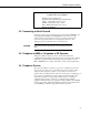
COM200 Telephone Modem Table 1. Dataloggers that Require Direct 12 VDC Connection to COM200 CR10(X) w/ silver wiring panel CR10(X) w/ black CR10 wiring panel (P/N 8032) 21X(L)—serial number 13,442 or lower CR500serial number 1764 or lower CR7—700X serial number 2778 or lower BDR301 and BDR320 3.2 Connecting to Earth Ground Connect the green 14 awg grounding wire (provided with the COM200) to the grounding terminal (GND) on the COM200 and to the enclosure’s earth ground connection.
COM200 Telephone Modem G 1 V 2 ogan,U L tah G 2 1 V P R E W O IN W S V 2 1C TR L 7 S E IF D 8 9 4 G G H 0 1 1 5 L A G H 2 1 W S V 2 1 6 L A G H L A G E 3 G A G G V 5 V 5 G SI/O C G XW 0 1 R C G N IR L E N A P EINU D A M A S S E IF D 1 2 3 L A G H G H 4 5 L A G H 2 1 G 6 M D S 3 L A G E 1 G A 2 E G 1 P G P 2 G C 8 7 C 6 C 5 C 4 C 3 C C 2 1 C G 2 V 1 V 2 1 EH T R A D N U O R G G N IR W LN E N A P . O C L E B P M A TIF N IE C S C .
COM200 Telephone Modem IF D G A H L A G 4 8 E S 7 H L G A H L G A 5 6 9 0 1 1 2 1 3 A E G G G G G G G V 2 1 V 2 1 ITC W S D E H V 2 1 G 2 1 V P R E W O IN CAME SCIENTIFIC INC. CR1 EINU D A M A S G N IR W LN E N A P .
COM200 Telephone Modem 4. Troubleshooting When the Campbell Scientific software cannot establish a link to the remote datalogger that is connected to the COM200, check the following: 1) Verify the modem initialization settings have been changed for the specific calling modem on the computer. See software manual and/or help screens for more information. 2) Verify nothing else is using the same COM port on the computer. Even if a program is minimized in windows, it may have a lock on the COM port.
COM200 Telephone Modem To comply with FCC Rules and Regulations, all repairs on the COM200 modem must be performed by Campbell Scientific, Inc. or an authorized agent of Campbell Scientific, Inc. For assistance in installation, troubleshooting, or for repair, contact Campbell Scientific: Campbell Scientific, Inc. 815 West 1800 North Logan, Utah 84321-1784 Telephone: (435) 753-2342 Fax: (435) 750-9540 Web site: www.campbellsci.com 5.
COM200 Telephone Modem This is a blank page.
Appendix A. Modifying the Non-Volatile Memory To modify the COM200’s settings, one must communicate directly to the COM200. This may be accomplished by using one of the two methods below. CAUTION Changing some of the modem's settings may result in communication problems. After changing the settings, try the modem locally before installing it at a remote location. A.1 Hardware Connection to COM200 Connect the COM200 to a computer using an SC532 interface (Figure A-1).
Appendix A. Modifying the Non-Volatile Memory A C2 A AC A A o o ed lac CA CC C. C Cable C Complies ith inger uiale art , CC rules. CC egist nce ..euired ration o. A Connecto r C C. Cana his euipmen dian oad o. computin t complies ith the g unaccep deice. peration of reuirements in art tabl hateer step e interference this euepment in of CC ules for Clas a residentia to radio sA s are nec and l area may essary to rece cause correct the ption reuiring the operato interferenc r to tae e.
Appendix A.
Appendix A. Modifying the Non-Volatile Memory COMMANDS TO CHANGE DEFAULT MODES: B1 (default) B0 CCITT V.32 (9600 baud), Bell 212A (1200 baud), and Bell 103 (300 baud) CCITT V.32 (9600 baud), CCITT V.22 (1200 baud), and CCITT V.21 (300 baud) S0=0 S0=1 S0=2 S0=X Disable Auto Answer Answer on first ring Answer on second ring th Answer on X ring.
Appendix B. CS I/O Connection B.1 CS I/O 9-Pin Connection The pin out of the connector is shown in Figure B-1. The direction of the signal relative to the modem is shown in parenthesis. Unless specified otherwise, all levels are 0 V for logic low, 5 V for logic high. FIGURE B-1. CS I/O Pin Out 1. (input) +5 VDC supply. Not used by COM200. 2. (input) Ground 3. (output) Ring - a logic high signifies a ring signal has been detected 4. (output) RX Data - serial data from COM200 5.
This is a blank page.
Appendix C. Theory of Operation C.1 Theory of Operation The COM200 modem is used to transmit data over bandwidth-limited channels such as telephone lines by modulating audio tones, using Phase Shift Keying (PSK) at 9600 or 1200 baud and Frequency Shift Keying (FSK) at 300 baud. The telephone company gives a 40 to 150 VRMS, 20 Hz signal on the telephone lines to signify a ring, which is typically on for 2 seconds and off for 4 seconds.
This is a blank page.
Appendix D. FCC Warning to Users of Class A Computing Devices WARNING This equipment generates, uses, and can radiate radio frequency energy, and if not installed and used in accordance with the instruction manual, may cause interference to radio communications.
This is a blank page.
Appendix E. IC Information NOTE Industry Canada (IC) was formally known as DOC. CP-01, Issue 8, Part I Section 14.1 “ NOTICE: The Industry Canada label identifies certified equipment. This certification means that the equipment meets certain telecommunications network protective, operational and safety requirements as prescribed in the appropriate Terminal Equipment Technical Requirements document(s). The Department does not guarantee the equipment will operate to the user’s satisfaction.
This is a blank page.
Appendix F. The 10704 12 V Adaptor COM200s prior to serial number 2334 require a part number 10704 adaptor to connect 12 volts directly to the modem. The 10704 adaptor is used between the SC12 cable and the datalogger (Figure F-1). Table F-1 lists the Campbell Scientific dataloggers that do not supply 12 VDC on the 9 pin connector and hence require a direct 12 VDC connection to the COM200. When using the 10704 adaptor, the red and black wires should be connected to 12 V and Ground, respectively.
This is a blank page.