
Instruction manual


COM200 Telephone Modem
2
• Current drain: 120 µA quiescent, 140 mA active
• Direct connection to and powered by CSI dataloggers
• Supply requirements: 12 VDC regulated power supply
• Internally switches 12 VDC external power minimizing current drain
• Logic levels: below 1.5 V inputs a low state and above 3.5 V inputs a
high state. A low voltage level on the TX data input (pin 9) and RX data
output (pin 4) represents a mark
• Operational temperature: -25
o
C to +50
o
C
• Size: 5.2” x 1.7” x 3.6” // 13.1 x 4.3 x 9.2 cm
• Weight: 0.75 lbs // 0.34 kg
TIP
RING
GND
CAMPBELL
SCIENTIFIC
INC.
COM200 MODEM
M
A
D
E
IN
U
S
A
S/N
1002
Complies with Part 68, FCC rules. FCC Registration No. B9QUSA-31402-MM-T
Ringer Equivalence 0.6B.Required Connector USOC RJ11C. Canadian Load No. 5
T
h
is e
q
u
ip
m
e
n
t co
m
p
lie
s w
ith
th
e
re
q
u
ire
m
e
n
ts in
P
a
rt 1
5
o
f F
C
C
R
u
le
s
fo
r C
la
ss A
c
o
m
p
u
tin
g
d
e
v
ic
e
. O
p
e
ra
tio
n
o
f th
is
e
q
u
ip
m
e
n
t in
a
re
s
id
e
n
tia
l a
re
a
m
a
y
c
a
u
s
e
unacceptable interference to radio and TV reception requiring the operator to take
w
hatever steps are necessary to correct the interference.
12V
G
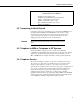
FIGURE 1. COM200
3. Installation
The COM200 is designed to be used with standard analog telephone lines. It
will not work with a digital telephone line. Connection to telephone company-
provided coin service (central office implemented systems) is prohibited.
Connection to party line service is subject to state tariffs.
3.1 Connecting to Datalogger
Connect the cable from the telephone RJ11C jack to the modem as shown in
Figure 3. If the telephone company has not installed surge protection in the
telephone line (no RJ11C jack), one must install surge protection (Model 6362
or 2372-01) and connect the ring and tip terminal blocks as shown in Figure 2.
Current Campbell Scientific dataloggers provide 12 VDC to the COM200 via
the SC12 cable (Figure 2). Older dataloggers do not provide 12 VDC on the
datalogger's CS I/O 9 pin connector. When used with the older dataloggers
listed in Table1, 12 VDC and ground need to be connected via the green power
connector on the side of the COM200 (see Figure 3).