
Operator`s manual


OV-1
CR7 MEASUREMENT AND CONTROL SYSTEM OVERVIEW
The CR7 Measurement and Control System combines precision measurement with processing and
control capability in a battery operated system.
Campbell Scientific, Inc. provides three documents to aid in understanding and operating the CR7:
1. This Overview
2. The CR7 Operator's Manual
3. The CR7 Prompt Sheet
This Overview introduces the concepts required to take advantage of the CR7's capabilities. Hands-on
programming examples start in Section OV4. Working with a CR7 will help the learning process, so
don't just read the examples, turn on the CR7 and do them. If you want to start this minute, go ahead
and try the examples, then come back and read the rest of the Overview.
The sections of the Operator's Manual which should be read to complete a basic understanding of the
CR7 operation are the Programming Sections 1-3, the portions of the data retrieval Sections 4 and 5
appropriate to the method(s) you are using (see OV5), and Section 14 which covers installation and
maintenance.
Section 6 covers the details of serial communications. Sections 7 and 8 contain programming examples.
Sections 9-12 have detailed descriptions of the programming instructions, and Section 13 goes into
detail on the CR7 measurement procedures.
The Prompt Sheet is an abbreviated description of the programming instructions. Once familiar with the
CR7, it is possible to program it using only the Prompt Sheet as a reference, consulting the manual if
further detail is needed.
Read the Selected Operating Details and Cautionary Notes at the front of the Manual before using the
CR7.
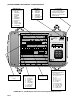
OV1. PHYSICAL DESCRIPTION
The CR7 features a modular, multiple
processor design that provides precision
measurement and control capability in a rugged,
battery operated system. Control Module
functions include real-time task initiation,
measurement processing, data storage,
telecommunications, and keyboard/display
interaction. The I/O Module performs all analog
and pulse signal measurement functions as well
as the analog and digital control output
functions. The I/O Module contains its own
processor card, a precision analog interface
card, and seven card slots which can
accommodate any combination of I/O Cards.
Sensor leads are connected to the I/O cards via
screw terminals.
A maximum of four I/O modules, separated by
up to 1,000 feet, may be connected to a single
Control Module in applications that require
distributed measurement capability.
OV1.1 700X CONTROL MODULE
Contains the CPU card, with 24K of system
PROM and 40K of RAM; the serial interface
card for peripheral communication and
connection of up to four I/O Modules; and the
keyboard display card. Two slots are present
for optional RAM expansion. The system's 2.5
Ahr lead-acid batteries and AC charging
circuitry are also contained in this module.
The CS I/O 9-pin port provides connection to
data storage peripherals, such as the
SM192/716 Storage Module, and provides
serial communication to computer or modem
devices for data transfer or remote
programming (Section 6). This 9 pin port does
NOT have the same pin configuration as the