RAWS-P Remote Automated Weather Station Revision: 6/10 C o p y r i g h t © 2 0 0 6 - 2 0 1 0 C a m p b e l l S c i e n t i f i c , I n c .
Warranty and Assistance The RAWS-P REMOTE AUTOMATED WEATHER STATION is warranted by Campbell Scientific, Inc. to be free from defects in materials and workmanship under normal use and service for twelve (12) months from date of shipment unless specified otherwise. Batteries have no warranty. Campbell Scientific, Inc.'s obligation under this warranty is limited to repairing or replacing (at Campbell Scientific, Inc.'s option) defective products.
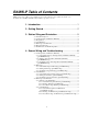
RAWS-P Table of Contents PDF viewers note: These page numbers refer to the printed version of this document. Use the Adobe Acrobat® bookmarks tab for links to specific sections. 1. Introduction..................................................................1 2. Getting Started.............................................................2 3. Station Siting and Orientation ....................................5 3.1 3.2 3.3 3.4 3.5 3.6 3.7 General Description ................................................
RAWS-P Table of Contents 4.5 Barometric Pressure ................................................................................. 9 4.5.1 General Description, Barometric Pressure (part #CS100-QD) ...... 9 4.5.2 Wiring, Barometric Pressure (part #CS100) .................................. 9 4.5.3 Troubleshooting, Barometric Pressure (part #CS100) ................. 10 4.6 Fuel Moisture and Fuel Temperature..................................................... 10 4.6.
RAWS-P Table of Contents 9. References .................................................................22 9.1 Specifications, Equipment and Sensor....................................................22 9.2 Siting References ....................................................................................22 9.3 RAWS Orientation .................................................................................22 9.3.1 Determining True North and Sensor Orientation..........................22 9.3.
RAWS-P Table of Contents iv
RAWS-P Remote Automated Weather Station 1. Introduction The RAWS environmental enclosure can be used for configuring a custom Remote Automated Weather Station (RAWS) that matches the requirements of your application. The aluminum environmental enclosure houses a 12 V rechargeable battery and a CR1000 datalogger. The outside of the enclosure has color-coded, keyed connectors (Figure 1-1) for attaching the sensors.
RAWS-P Remote Automated Weather Station 2. Getting Started 2 NOTE Set up and test your station before field deployment. NOTE Keep this manual and the CR1000KD Keyboard Display with the RAWS. Review the station siting and orientation section before field deployment. If a problem is encountered, review the equipment wiring and troubleshooting sections in this manual.
RAWS-P Remote Automated Weather Station CR1000KD Packed in Foam (may go here) Battery (1) Connect Battery (2) Turn on CH100 TX312 GOES Transmitter VSP3 Vosponder CS100 Barometric Sensor RF Radio SC12 Cable CR1000 Datalogger CR1000 Power In CR1000 Wiring Panel FIGURE 2-1. Inside Environmental Enclosure (optional equipment shown) NOTE The RAWS-P comes with a generic program.
RAWS-P Remote Automated Weather Station NOTE Use the CR1000KD Keyboard Display to see the “Public Variables” shown in Table 2-1. • • • • • • • • Connect the CR1000KD Keyboard Display to the CS I/O connector (Figure 5.
RAWS-P Remote Automated Weather Station 3. Station Siting and Orientation 3.1 General Description Selecting an appropriate site for the RAWS is critical in order to obtain accurate meteorological data. In general, the site should be representative of the general area of interest and away from the influence of obstructions such as buildings and trees. NOTE WARNING See Section 9 for siting references. If any part of the weather station comes in contact with power lines, you could be killed.
RAWS-P Remote Automated Weather Station 3.6 Barometric Pressure The barometric pressure sensor is mounted to the back plate inside the RAWS environmental enclosure. 3.7 Fuel Moisture and Fuel Temperature The fuel moisture and fuel temperature sensor should be left outside at the field site continually exposed to the same conditions as forest fuels. The fuel moisture and fuel temperature dowel rods absorb and desorb moisture from its surroundings.
RAWS-P Remote Automated Weather Station 4.2 Rain Gage 4.2.1 General Description, Rain Gage (part #TE525-LQ) The Texas Electronics Rain Gage (part #TE525-LQ) is an adaptation of a Weather Bureau tipping bucket rain gage. The rain gage has a 6 inch collector. The rain gage sensor output has a switch closure for each bucket tip. Level the rain gage. 4.2.2 Wiring, Rain Gage (part #TE525-LQ) The rain gage is connected to the RAWS connector panel “PRECIP” connector COLOR CODED BLUE.
RAWS-P Remote Automated Weather Station 4.3.3 Troubleshooting, Pyranometer (part #CS300-LQ) Check the sensor cable. Disconnect the connector and use a DVM to check the voltage between Pin A Solar Sensor (+) and Pin B Solar Sensor (-). The voltage should be 0 to 200 mV for 0 to 1000 Wm -2 radiation. No voltage indicates a problem with either the photodiode or the shunt resistor, both of which are potted in the sensor head and cannot be serviced. Try connecting a substitute sensor.
RAWS-P Remote Automated Weather Station 4.4.2 2-D WindSonic 4.4.2.1 General Description, 2-D WindSonic (part #WindSonic-LQ) The Gill Instruments 2-D Sonic Wind Sensor (part #WindSonic-LQ) is an ultrasonic anemometer for measuring wind direction and wind speed. It uses two pairs of orthogonally oriented transducers to sense the horizontal wind. The transducers bounce the ultrasonic signal from a hood, thus minimizing the effects of transducer shadowing and flow distortion.
RAWS-P Remote Automated Weather Station CS100 Barometric Pressure Sensor wires attached to CR1000 Wiring Panel CS100 Blue wire to CR1000 wiring panel 5H CS100 Yellow wire to CR1000 wiring panel AG CS100 Red wire to CR1000 wiring panel 12V CS100 Clear wire to CR1000 wiring panel Ground CS100 Black wire to CR1000 wiring panel Ground CS100 Green wire to CR1000 wiring panel C4 CAUTION The CS100 is sensitive to static when the back plate is removed.
RAWS-P Remote Automated Weather Station Connector Panel “FM/FT” connector COLOR CODED BROWN Connector Pin A CS205 Temp. Signal to CR1000 4L Connector Pin B Sensor Ground to CR1000 Ground Connector Pin C CS205 Temp. Excitation to CR1000 EX1 Connector Pin D CS505 FM Enable to CR1000 C8 Connector Pin E CS505 FM Signal to CR1000 4H Connector Pin F CS505 FM +12V power to CR1000 +12V 4.6.3 Troubleshooting, Fuel Moisture/Fuel Temperature (part #CS515-LQ) Check the sensor cable.
RAWS-P Remote Automated Weather Station 5.1.3 Troubleshooting, Solar Panel (part #SP10/20-LQ) If a problem with the solar panel is suspected, the solar panel may be checked by measuring the voltage output from the solar panel. Check the voltage with a voltmeter connected between the two leads going to the CH100 charger/regulator “CHG” “CHG” terminals located inside the environmental enclosure (15 VDC to 28 VDC).
RAWS-P Remote Automated Weather Station 5.2.2 Wiring, 12 V Charger/Regulator (part #CH100) The leads from the RAWS connector panel “BATT CHARGER/SOLAR PANEL” connector COLOR CODED PURPLE are wired to the CH100 “CHG” terminals. Polarity does not matter; either lead can be connected to either terminal. The charge indicating diode should be “ON” when voltage to the charging circuitry (CHG Terminals) is present.
RAWS-P Remote Automated Weather Station 5.3 Battery 5.3.1 General Description, Battery The RAWS battery is a rechargeable 12 Volt battery. The battery requires a regulated charging source provided by the RAWS Charger/Regulator (part #CH100) connected to an unregulated solar panel or a wall charger. WARNING RAWS rechargeable batteries are designed to be float charged. Permanent damage occurs and battery life is shortened if the battery is allowed to discharge below 10.5 volts. 5.3.
RAWS-P Remote Automated Weather Station The TX312 transmitter has two siting requirements for proper operation. The GOES antenna must have a clear view of the spacecraft. The GOES antenna is directional and should be aimed at the spacecraft. Both elevation and azimuth are unique to the location of the planet and must be set. A poorly aimed antenna will cause a drop in signal strength or possibly prevent successful transmission.
RAWS-P Remote Automated Weather Station 5.4.
RAWS-P Remote Automated Weather Station FIGURE 5.5-1. Voice Radio Interface 5.5.2 Wiring, Voice Radio Interface (part #VSP3) The Voice Radio Interface (part #VSP3) is mounted inside the RAWS environmental enclosure and the VSP3 connections are described below.
RAWS-P Remote Automated Weather Station 5.6 CR1000 Keyboard/Display 5.6.1 General Description, CR1000 Keyboard/Display (part #CR1000KD) The CR1000 Keyboard/Display (part #CR1000KD) shown in Figure 5.6-1 is used to check datalogger status, display or plot sensor readings and stored values, and to enter numeric data or change port/flag state.
RAWS-P Remote Automated Weather Station Obtain a Return Material Authorization (RMA) number before returning this equipment to Campbell Scientific for repair. NOTE Consult the CR1000 manual for more information. 5.7 CR1000 Datalogger (part #CR1000) 5.7.1 General Description, CR1000 Datalogger (part #CR1000) The CR1000 shown in Figure 5.7-1 provides sensor measurement, timekeeping, data reduction, data/program storage and control functions.
RAWS-P Remote Automated Weather Station 5.7.2 Wiring, CR1000 Datalogger (part #CR1000) The CR1000 datalogger is mounted inside the RAWS environmental enclosure and fastened to the CR1000 printed circuit board wiring panel. Connect 12 V power to the CR1000 printed circuit board wiring panel green power connector. The CH100 ON-OFF switch applies power to the 12 V terminals. 5.7.
RAWS-P Remote Automated Weather Station 7. Sensor and Equipment Maintenance 7.1 Sensor and Equipment Maintenance Proper maintenance of weather station components is essential to obtain accurate data. Equipment must be in good operating condition, which requires a program of regular inspection and maintenance. Routine and simple maintenance can be accomplished by the person in charge of the weather station. More difficult maintenance, such as sensor calibration, sensor performance testing (i.e.
RAWS-P Remote Automated Weather Station 9. References 9.1 Specifications, Equipment and Sensor Specifications are available from our web site at http://www.campbellsci.com/index.cfm. For “sensors specifications,” click on “Products”, select “Sensors” and go to the sensor manual for specifications. For “equipment specifications”, enter the part # in the “Search” box on the website mentioned above and go to the equipment manual for specifications.
RAWS-P Remote Automated Weather Station in Figure 9.3-3. Note that when a negative number is subtracted from a positive number, the resulting arithmetic operation is addition. For example, the declination for Longmont, CO is 10.1°, thus True North is 360° - 10.1°, or 349.9° as read on a compass. Likewise, the declination for Mc Henry, IL is -2.6°, and True North is 0° - (-2.6°), or 2.6° as read on a compass. FIGURE 9.3-1.
RAWS-P Remote Automated Weather Station FIGURE 9.3-2. A Declination Angle East of True North (Positive) is Subtracted from 360 (0) degrees to Find True North FIGURE 9.3-3. A Declination Angle West of True North (Negative) is Subtracted from 0 (360) degrees to Find True North 9.3.2 USGS Web Calculator The USGS provides an easy way of determining declination of a specific site. Since magnetic declination fluctuates with time, it should be adjusted each time the wind sensor orientation is adjusted.
RAWS-P Remote Automated Weather Station FIGURE 9.3-4. USGS Web Calculator In the example above the declination for Logan, UT is 12º 24′ or 12.4º. As shown in Figure 9.3-4, the declination for Utah is East (positive), so True North for this site is 360 – 12.4 = 347.6 degrees. The annual change is 7 minutes West per year or -7 minutes/year.
RAWS-P Remote Automated Weather Station 26
Campbell Scientific Companies Campbell Scientific, Inc. (CSI) 815 West 1800 North Logan, Utah 84321 UNITED STATES www.campbellsci.com • info@campbellsci.com Campbell Scientific Africa Pty. Ltd. (CSAf) PO Box 2450 Somerset West 7129 SOUTH AFRICA www.csafrica.co.za • cleroux@csafrica.co.za Campbell Scientific Australia Pty. Ltd. (CSA) PO Box 444 Thuringowa Central QLD 4812 AUSTRALIA www.campbellsci.com.au • info@campbellsci.com.au Campbell Scientific do Brazil Ltda.