HMP45C Temperature and Relative Humidity Probe User Guide Issued 27.5.09 Copyright © 1990-2009 Campbell Scientific Inc. Printed under Licence by Campbell Scientific Ltd.
Guarantee This equipment is guaranteed against defects in materials and workmanship. This guarantee applies for twelve months from date of delivery. We will repair or replace products which prove to be defective during the guarantee period provided they are returned to us prepaid.
PLEASE READ FIRST About this manual Please note that this manual was originally produced by Campbell Scientific Inc. primarily for the North American market. Some spellings, weights and measures may reflect this origin. Some useful conversion factors: Area: Length: 1 in2 (square inch) = 645 mm2 1 in. (inch) = 25.4 mm 1 ft (foot) = 304.8 mm 1 yard = 0.914 m 1 mile = 1.609 km Mass: 1 oz. (ounce) = 28.35 g 1 lb (pound weight) = 0.454 kg Pressure: 1 psi (lb/in2) = 68.95 mb Volume: 1 UK pint = 568.
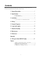
Contents PDF viewers note: These page numbers refer to the printed version of this document. Use the Adobe Acrobat® bookmarks tab for links to specific sections. 1. General Description .................................................... 1 2. Specifications .............................................................. 1 2.1 Temperature Sensor ..................................................................................2 2.2 Relative Humidity Sensor.....................................................
Tables 1. Connections for Single-Ended Measurements............................................6 2. Connections for Differential Measurements...............................................6 3. Power Connections using PSW12 Peripherals ...........................................7 4. Calibration for Temperature .......................................................................7 5. Calibration for Relative Humidity ..............................................................7 6.
HMP45C Temperature and Relative Humidity Probe 1. General Description The HMP45C Temperature and Relative Humidity probe contains a Platinum Resistance Temperature detector (PRT) and a Vaisala HUMICAP® 180 capacitive relative humidity sensor. The HMP45C can be powered continuously or the power may be switched to conserve battery life. The HMP45C consumes less than 4 milliamperes current at 12 volts. Approximately 0.15 seconds is required for the sensor to warm up after power is switched on.
HMP45C Temperature and RH Probe 2.1 Temperature Sensor Sensor: 1000 Ω PRT, IEC 751 1/3 Class B Temperature Measurement Range: -40°C to +60°C Temperature Output Signal range: 0.008 to 1.0 V Temperature Accuracy: Error ( o C) 0.4 0.2 0.0 -0.2 -0.4 -40 -20 0 20 40 60 o Temperature ( C) 2.2 Relative Humidity Sensor Sensor: HUMICAP® 180 Relative Humidity Measurement Range: 0 to 100% non-condensing RH Output Signal Range: 0.
User Guide CAUTION Do not overtighten the nut that holds in the probe as the probe could be damaged. Figure 1. HMP45C and 41003-5 Radiation Shield on a Tripod Mast 3.1 Specific instructions for the URS1 Radiation Shield A typical radiation shield for the HMP45C is shown in Figure 1. This shield, as sold by Campbell Scientific, is supplied with an adapter that enables the HMP45C to be fitted and detached as follows: 1. Loosen the large retaining nut at the bottom of the shield until it turns freely. 2.
HMP45C Temperature and RH Probe 5. Continue to carefully insert the probe a further 10mm, until the shoulder of the larger section is approximately level with the hole in the lowest curved disc, as shown in Figure 2 (b), below. 6. Tighten the large retaining nut by hand (do not use any tools) until the probe is firmly gripped. If the probe does not appear to be sitting squarely inside the shield, loosen the nut, re-position the probe and re-tighten.
User Guide CAUTION 1. Do not push the probe so far into the radiation shield that the sensor tip touches the top of the shield. 2. Ensure that your last action before tightening the large securing nut is not to withdraw the probe (i.e. do not pull in a downwards direction). This will cause the sealing membrane to also pull downwards and will form a well around the sensor which may then trap water.
HMP45C Temperature and RH Probe Table 1.
User Guide Table 3. Power Connections using PSW12 Peripherals HMP45C Description Colour PSW12 Peripheral Terminal Wire Datalogger Power Red 12V Red 12V Power Ground Black G Black* See tables 1&2 Control Port Yellow *The black wire of the PSW12 should be connected to the type of datalogger ground channel recommended for the HMP45C black wire as listed in Table 1 and 2. 5. Example Programs This section is for users who write their own datalogger programs.
HMP45C Temperature and RH Probe Table 6. Wiring for Single-ended Measurement Examples Description Temperature Relative Humidity Signal Reference Jumper from SW12V Control Power Power Ground Shield Colour White Green Blue CR1000 SE 2 (1L) SE 1 (1H) N/A Red Black Clear SW12 V CR10(X) SE 3 (2H) SE 4 (2L) AG C1 SW12 V AG G NOTE: These wire colours differ from HMP45C probes supplied in the USA.
User Guide CR10(X) Program using Single-Ended Measurement Instructions Using a PSW12 or SW12V on Datalogger ;Turn the HMP45C on. ; 01: Do (P86) 1: 41 Set Port 1 High ;Jumper wire from PSW12 control to C1 ;Yellow wire (C1) if using PSW12 device ;For CR23X or CR5000 use 49 for SW12V internal ;control port ;Pause 150 mSec before making measurements so the ;probe can stabilize on true readings. ; 02: Excitation with Delay (P22) 1: 1 Ex Channel 2: 0 Delay W/Ex (units = 0.
HMP45C Temperature and RH Probe 6. Long Lead Lengths This section describes the error associated with measuring the HMP45C with a single-ended measurement if the probe has a long cable. To avoid these problems, CSI recommends measuring the HMP45C using a differential analogue measurement (Instruction 2) when long lead lengths are required. Generic datalogger connections for measuring the HMP45C using a differential measurement are given in Table A-2.
User Guide CR1000 Program using Differential Measurement Instructions Using SW12 on Datalogger 'CR1000 program to measure HMP45C with differential measurements Public AirTC Public RH DataTable(Temp_RH,True,-1) DataInterval(0,60,Min,0) Average(1,AirTC,IEEE4,0) Sample(1,RH,IEEE4) EndTable BeginProg Scan(1,Sec,1,0) 'HMP45C Temperature & Relative Humidity Sensor measurements AirTC and RH: SW12 (1 ) Delay(0,150,mSec) VoltDiff (AirTC,1,mV2500,2,True,0,_50Hz,0.1,-40) VoltDiff (RH,1,mV2500,1,True,0,_50Hz,0.
HMP45C Temperature and RH Probe ;Measure the HMP45C temperature. ; 03: Volt (Diff) (P2) 1: 1 Reps 2: 5 2500 mV Slow Range 3: 4: 5: 6: 2 1 .1 -40 DIFF Channel Loc [ T_C ] Mult Offset ;Measure the HMP45C relative humidity. ; 04: Volt (Diff) (P2) 1: 1 Reps 2: 5 2500 mV Slow Range 3: 4: 5: 6: 1 2 .
User Guide in the air has not changed. Thus, the amount of water vapour in the air, relative to saturation, has decreased. Because of the inverse relationship between relative humidity and air temperature, finding the mean relative humidity is meaningless. A more useful quantity is the mean vapour pressure. The mean vapour pressure can be computed on-line by the datalogger (Example 3). Table 8.
HMP45C Temperature and RH Probe CR10(X) Program that Computes Vapour Pressure and Saturation Vapour Pressure ;Turn the HMP45C on. ; 01: Do (P86) 1: 41 Set Port 1 High ;Jumper wire from SW12V control to C1 ;Yellow wire (C1) if using PSW12 device ;For CR23X or CR5000 use 49 for SW12V internal ;control port ;Pause 150 mSec before making measurements so the ;probe can stabilize on true readings. ; 02: Excitation with Delay (P22) 1: 1 Ex Channel 2: 0 Delay W/Ex (units = 0.
User Guide ;Turn the HMP45C off. ; 05: Do (P86) 1: 51 Set Port 1 Low ;Compute the saturation vapour pressure. ;The temperature must be in degrees Celsius. ; 06: Saturation Vapour Pressure (P56) 1: 1 Temperature Loc [ T_C 2: 3 Loc [ e_sat ] ] ;Compute the vapour pressure. ;Relative humidity must be a fraction. ; 07: Z=X*Y (P36) 1: 3 X Loc [ e_sat ] 2: 2 Y Loc [ RH_frac ] 3: 4 Z Loc [ e ] 8. Maintenance The HMP45C Probe requires minimal maintenance.
HMP45C Temperature and RH Probe 9. Troubleshooting Symptom: -9999, NAN, -40 deg C, or 0% relative humidity 1. Check that the sensor is wired to the correct excitation and analogue input channels as specified by the measurement instructions. 2. Verify the Range code is correct for the datalogger type. 3. Verify the red power wire is correctly wired to the 12V, Switched 12V, or PSW12 module. The terminal the wire is connected to will depend on the datalogger program.
Appendix A. Wiring for Older HMP45C Probes Description Temperature Signal Relative Humidity Signal Signal Reference Power Control Power Power Ground Shield Colour Yellow Blue Purple Orange Red Black Shield Figure A-1. HMP45C Probe to Datalogger Connections Table A-1.
CAMPBELL SCIENTIFIC COMPANIES Campbell Scientific, Inc. (CSI) 815 West 1800 North Logan, Utah 84321 UNITED STATES www.campbellsci.com info@campbellsci.com Campbell Scientific Africa Pty. Ltd. (CSAf) PO Box 2450 Somerset West 7129 SOUTH AFRICA www.csafrica.co.za sales@csafrica.co.za Campbell Scientific Australia Pty. Ltd. (CSA) PO Box 444 Thuringowa Central QLD 4812 AUSTRALIA www.campbellsci.com.au info@campbellsci.com.au Campbell Scientific do Brazil Ltda.