INSTRUCTION MANUAL SC932 9-Pin to RS-232-DCE Interface Revision: 4/03 C o p y r i g h t ( c ) 1 9 8 7 - 2 0 0 3 C a m p b e l l S c i e n t i f i c , I n c .
Warranty and Assistance The SC932 9 PIN TO RS-232-DCE INTERFACE is warranted by CAMPBELL SCIENTIFIC, INC. to be free from defects in materials and workmanship under normal use and service for twelve (12) months from date of shipment unless specified otherwise. Batteries have no warranty. CAMPBELL SCIENTIFIC, INC.'s obligation under this warranty is limited to repairing or replacing (at CAMPBELL SCIENTIFIC, INC.'s option) defective products.
SC932 Table of Contents PDF viewers note: These page numbers refer to the printed version of this document. Use the Adobe Acrobat® bookmarks tab for links to specific sections. 1. General Description....................................................1 2. Specifications .............................................................2 3. Installation...................................................................3 3.1 3.2 3.3 3.4 Two Way Communication ......................................................
This is a blank page.
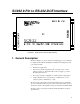
SC932 9-Pin to RS-232-DCE Interface FIGURE 1. SC932 9-Pin to RS-232-DCE Interface 1. General Description The SC932 (Figure 1) is used to interface a CSI datalogger to any modem that is configured with an RS-232 DCE (Data Communications Equipment) serial port. Features include: • True RS-232 signal levels. • Power for the SC932 is supplied from the 5 V supply on pin 1 of the datalogger’s I/O port. The SC932 will use the 5 V supply to power the RS-232 modem if needed.
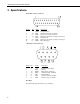
SC932 9-Pin to RS-232-DCE Interface 2. Specifications 25 Pin Male Connector Pin-out: Pin No. I/O 1 2 3 4 7 20 22 out in out out in Name Description GND TXD RXD RTS GND DTR RING Chassis Ground SC932 transmits data on this line SC932 receives data on this line Held active by SC932 (see jumper description Signal Ground Held active by SC932 (see jumper description Rings datalogger 9 Pin Male Connector Pin-out: Pin No.
SC932 9-Pin to RS-232-DCE Interface Electrical The SC932 uses power from the +5 V line on the 9 pin interface connected to the datalogger. The SC932 uses only a few microamps while inactive and about 5 mA when active from the 5 V supply. Additional current (up to 10 mA) from the 5 V supply may be used by the RS-232 device connected to the SC932. Physical Height: Width: Length: Weight: Mounting: 1.0 in (25 mm) 3.5 in (90 mm) 4.1 in (103 mm) 4.
SC932 9-Pin to RS-232-DCE Interface 3.2 One Way Communication 1. Remove the SC932 lid by removing the screw from the top of the box. 2. Jumper P3 between pins 3-4 to set the SC932 to one way data only. The SC932 is activated by pin 6 synchronous device enable (SDE) on the datalogger’s serial I/O port. See Figures 2 and 3. 3. Select the jumper configuration of P2 and P4 that will minimize power requirements and yet still allow the SC932 to function.
SC932 9-Pin to RS-232-DCE Interface P2 P3 P4 FIGURE 2. SC932 Jumper Locations FIGURE 3.
SC932 9-Pin to RS-232-DCE Interface 3.4 Jumper Descriptions The following guidelines are used to determine the proper jumper configuration for the modem being used. When selecting a jumper configuration always try to keep current drain to a minimum. Current Drain LO MEDIUM HIGH 6 Jumper Position Description P3 1-2 Allows SC932 to act as a Datalogger Modem device (two way communication). SC932 is activated by modem enable (ME) line.
SC932 9-Pin to RS-232-DCE Interface 4. RAD Modem Application The SC932 is most frequently used with a short range modem to communicate across a 4-wire, unconditioned dedicated line. This section describes the details of this application using a short range asynchronous modem built by RAD*. * SRM - 5A RAD Modem RAD Data Communications Inc. 900 Corporate Drive Mahwah, NJ 07430 Tel: (201) 529-1100 Fax: (201) 529-5777 Email: market@radusa.com http://www.rad.
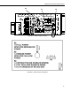
SC932 9-Pin to RS-232-DCE Interface The SC932 leaves the factory with the jumpers set as shown in Figure 4. In this mode, the SC932 and RAD modem combined will require about 2 mA while inactive and less than 20 mA while active. When using Campbell Scientific’s PC208W telecommunications software to communicate through the SC932/RAD modem, “Setup” the link as a direct connect between the datalogger and the desired COM port.
SC932 9-Pin to RS-232-DCE Interface 4.3 RAD Modem - Two Way or One Way FIGURE 6. Two Way or One Way Communication In the jumper configuration shown in Figure 6, the communication mode, two way or one way is determined by the modem enable line. Communication is two way if the modem enable line is high, one way if modem enable is low. In this mode, the SC932 and RAD modem combined will require about 2 mA while inactive and less than 20 mA while active. Two way setup and connect: same as two way only.
SC932 9-Pin to RS-232-DCE Interface transient protection shown may be purchased from Campbell Scientific, Inc. (p.n. 5563 shown in Figure 7, p.n. 6536 includes a plastic case, p.n. 6361 includes hardware for mounting to ground lug of CSI enclosures models ENC 10/12, ENC 12/14, or ENC 16/18). Spark gap wiring is straight through such that pin to pin continuity exists between the two modems. If the modems are installed entirely within a building, the transient spark gap protection is probably not needed.
SC932 9-Pin to RS-232-DCE Interface Occasionally a customer needs to transmit data across longer or smaller gage wires or at higher speeds than can be done with the RAD modem powered by the SC932. RAD does sell a 9 volt power supply that will boost the signals enough to meet some of these more demanding applications. Please contact RAD for more information. 4.
SC932 9-Pin to RS-232-DCE Interface 6. To verify that the datalogger and its serial I/O port are working, try to access input memory locations using a laptop PC with the SC32B or the CR10KD Keyboard Display. If the datalogger passes tests 4, 5, and 6, then the SC932 is suspect and will need to be repaired or replaced.
This is a blank page.
Campbell Scientific Companies Campbell Scientific, Inc. (CSI) 815 West 1800 North Logan, Utah 84321 UNITED STATES www.campbellsci.com info@campbellsci.com Campbell Scientific Africa Pty. Ltd. (CSAf) PO Box 2450 Somerset West 7129 SOUTH AFRICA www.csafrica.co.za sales@csafrica.co.za Campbell Scientific Australia Pty. Ltd. (CSA) PO Box 444 Thuringowa Central QLD 4812 AUSTRALIA www.campbellsci.com.au info@campbellsci.com.au Campbell Scientific do Brazil Ltda.