
Instruction manual


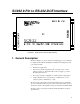

SC932 9-Pin to RS-232-DCE Interface
6
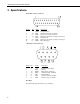
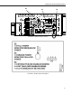
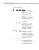
3.4 Jumper Descriptions
The following guidelines are used to determine the proper jumper configuration
for the modem being used. When selecting a jumper configuration always try
to keep current drain to a minimum.
Current
Drain
Jumper Position Description
P3 1-2 Allows SC932 to act as a Datalogger
Modem device (two way communication).
SC932 is activated by modem enable
(ME) line.
3-4 Allows SC932 to act as a Datalogger
Printer device (one way). SC932 is
activated by pin 6 synchronous device
enable (SDE) on the datalogger’s Serial
I/O port.
1-2 3-4 Allows SC932 to act as both of the above.
The one way data mode resumes once the
modem enable (ME) is dropped. The ME
line is dropped when the two way
communication is shut down or after 40
seconds of inactivity.
LO P2 Open
P4 Open DTR and RTS are held at 9V while the
SC932 is active. They are not driven
while the SC932 is not active. This
jumper selection should be used when the
SC932 is being used for Printer data or
when the RS-232 device connected to the
SC932 can produce a ring or RXD signal
while DTR, RTS, and TXD are not
powered (e.g. Hayes Modem).
MEDIUM P2 Open
P4 Installed DTR and RTS are held at 4.3V while the
SC932 is not active and 9V while active.
This jumper selection should be used
when the RS-232 device connected to the
SC932 can produce a ring or RXD signal
when DTR and RTS are at 4.3V and TXD
is not driven. This configuration will take
more power than when both P2 and P4 are
open depending on the RS-232 device
(e.g. RAD modems).
HIGH P2 Installed
P4 Open DTR and RTS are held at 9V all the time.
This configuration takes the most power,
and provides fully active RS-232 signals
on the DTR, RTS, and TXD lines all the
time. Any RS-232 compatible device
should work with this jumper selection.