TLX106 WEATHER STATION INSTRUCTION MANUAL 3/01 COPYRIGHT (c) 1993-2001 CAMPBELL SCIENTIFIC, INC.
This is a blank page.
Warranty and Assistance The TLX106 WEATHER STATION is warranted by CAMPBELL SCIENTIFIC, INC. to be free from defects in materials and workmanship under normal use and service for twelve (12) months from date of shipment unless specified otherwise. Batteries have no warranty. CAMPBELL SCIENTIFIC, INC.'s obligation under this warranty is limited to repairing or replacing (at CAMPBELL SCIENTIFIC, INC.'s option) defective products.
This is a blank page.
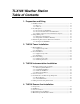
TLX106 Weather Station Table of Contents 1. Preparation and Siting 1.1 Installation Tasks .................................................................................. 1-1 1.1.1 Indoors......................................................................................... 1-1 1.1.2 Outdoors ...................................................................................... 1-1 1.2 Tools Required ...................................................................................... 1-1 1.2.
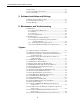
TLX106 Weather Station Table of Contents 4.6 Pyranometer ..........................................................................................4-3 4.7 Sensor Verification and Clock Set.........................................................4-3 4.8 Sensor Schematics .................................................................................4-4 5. Software Installation and Settings 5.1 Measure Sensors and Process Data .......................................................5-1 5.
TLX106 Weather Station Table of Contents 5.3-1 ProLine software provides an easy-to-use message editor ................ 5-7 5.3-2 The available options provided by the source menu are shown ........ 5-8 5.3-3 When the weather station source has been chosen, several meteorological conditions reported in various units are provided under the field menu ......................................................
This is a blank page.
Section 1. Preparation and Siting These guidelines apply to several Campbell Scientific weather stations. 1.1 Installation tasks 1.1.1 Indoors • Immediately upon receipt of your shipment… ⇒ Open shipping cartons. ⇒ Check contents against invoice. Contact CSI immediately about any shortages.
Section 1. Preparation and Siting 1.2.1 Tools for Tower Installation All Towers Shovel Rake Open end wrenches: 3/8", 7/16", ½", (2) 9/16" Magnetic compass 6' Step ladder TLX106 Tower Tape measure (12’ to 20’) Claw hammer Level (24” to 36” ) Hand saw Materials for concrete form: (4) 1" x 2" x 12" stakes (2) 2" x 4" x 96" lumber (12) 8p double-head nails (8) 16p double-head nails 20 ft form wire ½ Yard concrete Concrete trowel, edger Electrical Fish tape or 20 feet of small diameter rope Wheelbarrow 1.2.
Section 1. Preparation and Siting 1.2.3 Supplies for Power and Communications Options AC Power Wire, conduit, and junction boxes as needed Phone Modem Hayes compatible calling modem for PC Phone line to weather station or junction box Short-Haul Modem 4 Conductor communications cable from PC to weather station or junction box 6' copper ground rod and clamp for PC surge protection (optional) 1.
Section 1. Preparation and Siting Situations to avoid include: • large industrial heat sources • rooftops • steep slopes • sheltered hollows • high vegetation • shaded areas • swamps • areas where snow drifts occur • low places holding standing water after rains MADE IN USA eight of tree ogan Uta FIGURE 1.3-1. Effect of Structure on Wind Flow 1.
Section 1. Preparation and Siting (Section 1.4.1). A general map showing magnetic declination for the contiguous United States is shown in Figure 1.4-1. Declination angles east of True North are considered negative, and are subtracted from 0 degrees to get True North as shown Figure 1.4-2. Declination angles west of True North are con-sidered positive, and are added to 0 degrees to get True North as shown in Figure 1.4-3. For example, the declination for Logan, Utah is 16° East.
Section 1. Preparation and Siting Telephone numbers: Phone Number Baud Rates 303-273-8672 303-273-8673 303-273-8678 2400 1200 1200 Upon carrier-signal detection, press Return once or twice. If you are using one of the commercial numbers, the following prompts will appear.
Section 1. Preparation and Siting Exiting: Press "Cntrl-Z" to exit GEOMAG. When the main menu reappears either select another option or type "X" to log out. If you used one of the commercial numbers, the GLDSV1> prompt will reappear. Type "LO" to disconnect. Use of GEOMAG is free (except for telephone charges). If possible, please avoid using GEOMAG between 9 a.m. and 4 p.m., mountain time, Monday through Friday. The declination in the example above is listed as 15 degrees and 59.6 minutes.
Section 1. Preparation and Siting FIGURE 1.4-3.
Section 2. TLX106 Tower Installation DANGER Do not install near power lines. If any part of the tower comes in contact with power lines you could be KILLED. Contact local utilities for the location of buried utility lines before digging or driving grounding rods. CAUTION Do not fit the 3 meter TLX106 Tower sections together until the appropriate time. Once attached, they cannot be detached. The TLX106 Tower provides a support structure for mounting the TLX106 weather station components. Figure 2.
Section 2. TLX106 Tower Installation 2.1 Base Installation 2.1.1 Supplied Components (3) ½ inch L-Bolts (9) ½ inch Nuts (1) Anchor Template Refer to Section 1 for components supplied by installer. 2.1.2 Installation 2-2 1. The TLX106 Tower attaches to a user supplied concrete foundation constructed as shown in Figure 2.1-2. 2. Construct the concrete form with 2" x 4" lumber and 16p nails. 3. Assemble the template and anchor bolts.
Section 2. TLX106 Tower Installation D O TO O OT O OLT LL T TD O TLT FIGURE 2.1-2. TLX106 Tower Base Installation 2.2 Tower Installation 2.2.1 Supplied Components (1) Upper Tower Section (Tapered) (1) Lower Tower Section (6) ½ inch Washers (1) 12 foot 12 AWG Ground Cable (1) Tower Cap (1) 20' communications cable (1) 20' power cable Refer to Section 1 for components supplied by installer. 2.2.2 Installation Attach the tower to the base as shown in Figure 2.2-1. 1.
Section 2. TLX106 Tower Installation 4. Cut and save a 9 inch piece of 12 AWG ground wire from the 12 foot length provided. Thread the remaining 11 foot ground wire through the tower. Secure all wiring so it does not slip back into the tower or conduit. 5. Place the tower cap over the tower end. 6. Raise the tower on a still day. Place a washer on top of the two nuts on each foundation bolt.
Section 2. TLX106 Tower Installation 2.3.2 Grounding Procedure Ground the tower as shown in Figure 2.2-1. 1. Place the ground rod clamp on the rod. Secure it about 3 inches from the top. Do this before the rod is driven into the ground. Be careful not to damage the clamp with the hammer 2. Taking care not to damage power or communications lines, drive the ground rod close to the foundation using a fence post driver or sledge hammer. Drive the rod at an angle if an impenetrable hardpan layer exists.
This is a blank page.
Section 3. TLX106 Instrumentation Installation The weather station datalogger, power supply, sensor connection panel, communications devices, and data retrieval peripherals are mounted in the TLX106 enclosure at the locations shown in Figure 3-1. Components include: (1) TLX106 Enclosure (1) 4 unit Desiccant Pack (1) Flat Point Screw Driver (1) Philips Screwdriver (1) Power Supply Option (1) Telecommunications Option (1) 9 inch piece of 12 AWG ground wire (1) Lightning rod and clamp TLX106 FIGURE 3-1.
Section 3. TLX106 Instrumentation Installation 3.1 Enclosure, Datalogger, Power Supply 3.1.1 Battery Option Installation Solar Panel or 16 VAC Power Cable S FIGURE 3.1-1. Rechargeable Power Mounting and Connections a) NOTE Sealed Rechargeable Battery Option: Install the kit as shown in Figure 3.1-1. An unregulated solar panel or 17 to 24 VAC must be used with the rechargeable battery at all times.
Section 3. TLX106 Instrumentation Installation The solar panel should be oriented to receive maximum insolation over the course of the year. Suggested tilt angles (referenced to the horizontal plane) are listed below. b) Site Latitude Tilt Angle 0 to 10 degrees 10 degrees 11 to 20 Latitude + 5 degrees 21 to 45 Latitude + 10 degrees 46 to 65 Latitude + 15 degrees >65 80 degrees After determining the tilt angle, loosen the two bolts that attach the mounting bracket to the panel.
Section 3. TLX106 Instrumentation Installation 9-inch Ground Wire ORT H Tower Ground Wire FIGURE 3.1-3. Mounting and Grounding the TLX106 Enclosure c) Slide the enclosure to the top of the TLX106 tower. Position it on the north side of the tower (northern hemisphere). The top of the enclosure should be flush with the top of the tower, with the width of the sensor arm extending above the tower. Tighten the clamps until the enclosure is snug.
Section 3. TLX106 Instrumentation Installation Earth Ground Stand off Connector Sensors #4 TEMP CS615 #2 WS/WD #6 SDI 12 GYP BLOCK #7 TEMP #5 RAIN (PRECIP) #1 TEMP / RH #3 SOLAR RADIATION #8 COMM CS I/O POWER CABLE PORT STAND OFF COAXIAL CONNECTION FIGURE 3.2-1. Position of Sensor Bulkhead Connectors 3) Replace the protective connector cover after sensors are connected and power and communications cables are installed.
Section 3. TLX106 Instrumentation Installation If you received a telecommunications kit separate from the TLX106 Enclosure, follow the "Internal Installation" procedures outlined below. 3.3.1 Phone Modems Phone modems enable communications between the TLX106 Enclosure and a Hayes compatible modem in your PC over a dedicated phone line. Phone line surge protection in built into the TLX106 Enclosure. P/N 10588 Cable RJ11 Patch Cord Ground Wire Modem FIGURE 3.3-1.
Section 3. TLX106 Instrumentation Installation 3.3.1.2 External Installation The following modem kit components are used to make the external connections: (1) Direct Burial Splice Kit (1) 20 foot Telephone Patch Cord with Connector 1) Connect the 20 foot patch cord to the connector marked "comm" on the external back panel, under the protective cover. 2) Splice the labeled "Tip" and "Ring" lines of the patch cord to the telephone service line.
Section 3. TLX106 Instrumentation Installation 3. Connect the SC932C 9-pin port to the internal TLX106 Enclosure 9-pin port with the blue ribbon cable provided. 4. Wire the Rad Modem to the TLX106 Enclosure with the 12 inch patch cord. Match wire labels to wiring panel labels on both the TLX106 Enclosure and the Rad Modem (+XMT to +XMT, etc.). A small screw driver in provided with the TLX106 Enclosure to access the Rad Modem connections. 3.3.2.
Section 3. TLX106 Instrumentation Installation - RCV (white) TLX106 ENCLOSURE ET106 ENCLOSURE - XMT (black) EBPMAC DT CIITNEICS 551E NS - 239CS TLX106 ET106 ENCLOSURE ENCLOSURE C + RCV (green) + XMT (red) + RCV (red) - RCV (black) + XMT (green) - XMT (white) To # 8 External Connector Surge Protector PC SRM-5A 1 + RCV (red) - RCV (black) 2 User Supplied Cable Splices 1 + RCV RED 2 - RCV BLACK + XMT (green) 3 - XMT (white) 3 4 4 + XMT GREEN - XMT WHITE Earth Ground FIGURE 3.3-3.
Section 3.
Section 4. TLX106 Sensor Arm Installation 4.1 Components (1) TLX106 Sensor Arm (1) Met One 034A Wind Sensor (1) 034A Mounting Shaft (1) Radiation Shield 4.2 Installation Install the TLX106 Sensor Arm after the Enclosure is mounted low on the Tower. You may need to temporarily remove communications option. Mount the sensor arm as shown in Figure 4.2-1 without the wind sensor attached. ET Sensor Arm ET Enclosure Screws (4) FIGURE 4.2-1. TLX106 Sensor Arm Mounting 1) Remove the cover from the Enclosure.
Section 4. TLX106 Sensor Arm Installation 4.3 Sensor Connection Refer to Section 3 for sensor connection details. 4.4 034A Wind Sensor Installation Install the 034A Wind Sensor as shown in Figure 4.4-1 after the sensor arm is securely installed. The wind vane is oriented after the datalogger has been programmed, and the location of True North has been determined (Section 1.2).
Section 4. TLX106 Sensor Arm Installation 4.5 RH and Temperature Radiation Shield Mount the radiation shield to the sensor arm as shown in Figure 4.4-1. Remove yellow cap. Place the RH and temperature assembly inside the shield shaft. Attach the shield to the sensor arm with the two screws. 4.6 Pyranometer Level the pyranometer as indicated in Figure 4.6-1. Adjust the three leveling screws until the bubble level indicates plumb. Remove the red cap from the pyranometer. Leveling Screws FIGURE 4.6-1.
Section 4. TLX106 Sensor Arm Installation Input Location Parameter Normal Range 1 Enclosure Temperature (°C) Close to air temperature 3 Solar Radiation -2 (kW m ) 0 to 1.2 kW m 4 Air Temperature (°C) -40° to +50° 5 RH (%) 0 to 100% 6 Wind Speed (mph) 0 to 110 mph 7 Rain Fall (inches) 0 to .2 8 Wind Direction (°) 0 to 359 10 Battery (Volt) 9.6 to 14.
Section 4. TLX106 Sensor Arm Installation 3 4 2 6 5 1 Connector Pin Air Temperature and Relative Humidity Sensor Relative Humidity (0-1VDC) 1 Air Temperature (0-1VDC) 2 Not Used 3 12V Switched Supply 4 Analog Ground 5 Shield 6 Datalogger 1H 1L 12VDC Switched Supply AG G FIGURE 4.8-1.
Section 4. TLX106 Sensor Arm Installation 3 4 2 6 1 5 Connector Pin Solar Radiation Sensor Datalogger 1 3H 40.2 - 90.2 OHM 2 3L Not Used 3 Not Used 4 Not Used 5 6 Shield G FIGURE 4.8-3. Schematic of LI200X-LC Solar Radiation Sensor and Connector #3 Connector Pin Tipping Rain Bucket Not Used 1 3 4 2 6 Not Used 2 Not Used 4 Pulse 3 Ground 5 1 5 Datalogger Magnetically Activated Reed Switch Shield P2 G 6 G FIGURE 4.8-4.
Section 5. Software Installation and Settings 5.1 Measure Sensors and Process Data A pre-written datalogger program (PN 14079) comes installed in the TLX106. This program sets the scan rate, measures the sensors, processes internally and stores the data. This program will be factory corrected for the station’s latitude, longitude, elevation, and standard time meridian, and then downloaded to the station before shipping. 5.
Section 5. Software Installation and Settings Here again the Communications Enabled button must be selected. Then select the proper Modem Type and zero out the Extra Response Time. Then press Apply and continue to the next step. Here again the Communications Enabled must be selected. Then add the appropriate Phone Number. Then zero out the Maximum Time On Line box. This will make the maximum time on line indefinite. Leave the Packet Size and Extra Response Time at default.
Section 5. Software Installation and Settings The final termination must be to a CR10X-TD logger. The Proline will default to work with a logger named ‘lgr1’, but you can change this default if you want to name your logger something else. Change the logger name here and then refer to the RDE extra settings to make sure you change the name there so that the RDE will be able to find the logger with the appropriate data.
Section 5. Software Installation and Settings If not already started, start the LoggerNet server by double clicking the blue icon. Then start the Control Panel. It should automatically connect to the server. Then select the appropriate logger and click on the Connection bar. The computer should initiate and connect with the station. Then pull down the Options menu, go to Advanced, and then select Update Table Definitions. This procedure may take a minute as the weather station updates LoggerNet.
Section 5. Software Installation and Settings “ Keep Logger On Line” This is used to force LoggerNet to stay connected to the station the entire time the LoggerNet server is open. This is desirable when there are short collection intervals. The default settings are shown below. The Host is the computer that is running LoggerNet. This is why the “ LocalHost” is shown in this case as LoggerNet is running on the same machine as the RDE. The Port setting will almost always be set to 6789.
Section 5. Software Installation and Settings Now reopen Net Admin and go to the logger previously set up. Now we will check to see if the Table Definitions have updated correctly by going to the Data Collection tab. It could look like the following picture. Now select the Scheduled Collection tab again. Here you need to enable the scheduled collection by selecting the Scheduled Collection Enabled box.
Section 5. Software Installation and Settings 5.3 Create Message Perform the following steps using the Message Editor provided in ProLine Software: 1. Type the message in the area indicated in Figure 5.3-1. 2. Move cursor to where you want data inserted. 3. Select a source from the Source pull-down menu (Figure 5.3-2). 4. Select the desired field (Figure 5.3-3). 5. Click on the white cross (Figure 5.
Section 5. Software Installation and Settings FIGURE 5.3-2. The available options provided by the source menu are shown. FIGURE 5.3-3. When the weather station source has been chosen, several meteorological conditions reported in various units are provided under the field menu.
Section 6. Maintenance and Troubleshooting These guidelines apply to several Campbell Scientific weather stations. 6.1 Maintenance Proper maintenance of weather station components is essential to obtain accurate data. Equipment must be in good operating condition, which requires a program of regular inspection and maintenance. Routine and simple maintenance can be accomplished by the person in charge of the weather station.
Section 6. Maintenance and Troubleshooting 6.1.4 Sensor Maintenance Sensor maintenance should be performed at regular intervals, depending on the desired accuracy and the conditions of use. A suggested maintenance schedule is outlined below. 1 week • Check the pyranometer for level and contamination. Gently clean, if needed. • Visually inspect the wind sensors and radiation shield. 1 month • Check the rain gage funnel for debris and level.
Section 6. Maintenance and Troubleshooting 2. Punch a very small hole in the bottom of the can. 3. Place the can in the top funnel of the rain gage and pour 16 fluid ounces (1 pint) of water into the can. (A 16 oz. soft drink bottle filled to within 2.5 inches of the top may be used for a rough field calibration. An exact volume will allow for a more precise calibration). 4. If it takes less than 45 minutes for this water to run out, the hole in the can is too large. 5.
Section 6. Maintenance and Troubleshooting At the computer: D. Make sure the Station File is configured correctly. E. Check the cable(s) between the serial port and the modem. If cables have not been purchased through Campbell Scientific, check for the following configuration using an ohm meter: 25-pin serial port: computer end modem end 2 3 7 20 2 3 7 20 9-pin serial port: computer end modem end 2 3 4 5 3 2 20 7 F. Make sure the modem is properly configured and cabled (Section 6.6). G.