
Service manual


6
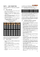
Table 4: DynaMax HS Floor Mount Service Clearances
Model
Service Clearance, Inches (cm)
Front Top Right Side Left Side Rear
210
12” (31cm) 24” (61cm) 0” (0cm) 12” (31cm) 14” (36 cm)
260
12” (31cm) 24” (61cm) 0” (0cm) 12” (31cm) 14” (36 cm)
299
12” (31cm) 24” (61cm) 0” (0cm) 12” (31 cm) 14” (36cm)
399
12” (31cm) 24” (61cm) 0” (0cm) 12” (31 cm) 14” (36 cm)
500
12” (31cm) 24” (61cm) 0” (0cm) 12” (31 cm) 14” (36 cm)
600
12” (31cm) 24” (61cm) 0” (0cm) 12” (31 cm) 14” (36cm)
700
12” (31cm) 24” (61cm) 0” (0cm) 12” (31 cm) 14” (36 cm)
800
12” (31cm) 24” (61cm) 0” (0cm) 12” (31 cm) 14” (36 cm)
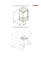
Figure 4: DynaMax HS Floor Mount Model Dimensions
Table 5: Appliance Dimensions and Specifications
Model
Dim.
"A"
[in.]
Dim.
"B"
[in.]
Dim.
"C"
[in.]
Dim.
"D"
[in.]
Dim.
"E"
[in.]
Dim.
"F"
[in.]
Dim.
"J"
[in.]
Equivalent Length of Vent & Air Intake
Pipes at Recommended Diameter, [in.]
Water
Conn.
at
Heater
[in.]
NPT
Gas
Conn.
at
Boiler
[in.]
NPT
Category IV
CAT.II
Comb.
Vents
Over 25'
and up
to 100'
Over 15'
and up
to 25'
Up to
15'
210
36 22 3/4 14 1/4 23 24 1/4 34 1/4 32 3 3 2 4 1 1/2
260
36 22 3/4 14 1/4 23 24 1/4 34 1/4 32 3 3 2 4 1 1/4 1/2
299
47 1/8 34 7/8 14 23 29 7/8 33 7/8 32 4 3 3 5 1 1/4 3/4
399
47 1/8 34 7/8 14 23 29 7/8 33 7/8 32 4 3 3 5 1 1/2 1
500
47 1/8 34 7/8 14 23 29 7/8 33 7/8 32 4 3 3 6 1 1/2 1
600
47 1/8 36 1/4 14 23 30 3/4 38 40 1/2 4 3 3 6 2 1
700
47 1/8 36 1/4 14 23 30 3/4 38 40 1/2
4 (Air), 6
(Vent)
4 4 7 2 1
800
47 1/8 36 1/4 14 23 30 3/4 38 40 1/2
5 (Air), 6
(Vent)
5 5 7 2 1
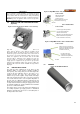
Maintain minimum specified clearances for adequate operation. All installations must allow sufficient space for servicing the vent
connections, water pipe connections, circulating pump, bypass piping and other auxiliary equipment, as well as the appliance