
Service manual

21
PART 6 CONTROL PANEL
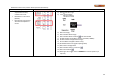
6.1 DYNAMAX HS CONTROLLER
The appliance is provided with an operator interface panel at
the front. On a DynaMax HS Wall Hung boiler the DynaMax
HS Controller can be accessed by removing the upper
stainless steel jacket and the lower black sheetmetal jacket
which are each held on by two (2) screws. On a DynaMax
HS Floor Mount boiler the DynaMax HS Controller can be
accessed by carefully lifting off the black-coloured top cover
which is held on by four (4) snap lock fasteners.
6.2 SETTING THE DYNAMAX HS
CONTROLLER
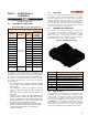
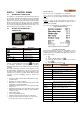
Button
Description
Back button to return to
previous menu
Information button
Home Button returns screen
to home screen
Navigation buttons
Confirm selection
The 5-way control pad allows for easy access to various
functions on the DynaMax HS controller. A button allows
for immediate information concerning boiler operation
including temperatures, boiler status and any errors that are
occurring.
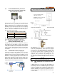
The Boiler Temperature Controller for this appliance is the
Honeywell SOLA. It initiates the local call for heat and sets
the target return (appliance inlet) water temperature. This
controller offers a range of operation modes which provides
set point as well as modulating control. It provides the
following:
• Readings of inlet and outlet water temperatures as well
as flame signal.
• Operation as an auto reset limit.
• Operation as a control for inlet water temperature, outlet
temperature, system temperature.
• Available tank mounted sensor used in conjunction with
inlet sensor.
• Adjustable; target temp, inter-stage differential, on delay
between stages, minimum on time per stage, minimum
off time per stage.
• Flame failure signal.
• Error message display in text
• Manual override of boiler input rate for combustion
• Pump exercising feature runs pump 10 seconds every
three days in the event of no pump operation.
Levels of Access
Two levels of access to simplify the use of the boiler.
User – Access to general boiler and display settings and
adjustments to the central heating and domestic hot water
setpoint.
Installer – Access to all user parameters and allows for
changes to additional boiler parameters to allow for ease of
startup and serviceability.
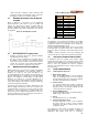
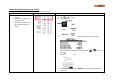
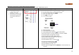
The screenshot below displays the default homescreen.
Figure 24: Home Screen
The first five parameters can be user customizable to reflect
the most vital information required on the boiler. The list of
available parameters is outlined in the table below. This can
be done by pressing:
1)
2) Scroll to Display Setup, press
3) Select the line item that is required to be altered,
press
4) Select parameter, and press
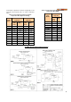
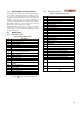
PARAMETER DESCRIPTION
Standard parameters
System setpoint Indicates active setpoint
Operating temp
Indicates temperature at modulation sensor
(Default: inlet sensor)
Outlet Outlet Water Temperature [
o
F]
Inlet Inlet Water Temperature [
o
F]
Outdoor Outdoor Temperature [
o
F], if equipped
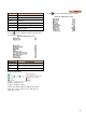
Additional user configurable parameters
Delta T
Outlet and Inlet water temperature differential
[
o
F]
LL Operating
Temp
Indicates temperature at modulation sensor, if
equipped (Default: S5: system sensor)
LL system
setpoint
Indicates active lead lag setpoint
Fan speed Actual fan speed [RPM]
Flame signal Actual flame signal [Vdc]
Firing Rate Target fan speed [RPM]
DHW DHW Temperature [
o
F] ], if equipped
Stack Stack Temperature [
o
F], if equipped
4-20mA 4-20mA input, if equipped