
Service manual


42
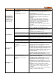
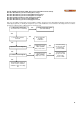
SYMPTOM FAILURE MODE ANALYSIS
Temperature
Overshoot
• Stack temperature has exceeded
the limit set on the boiler.
• Alert 125, 353
• PVC: Reduce desired setpoint to less than 140
o
F.
• Measure the resistance of the flue sensor at room
temperature, it should be approximately 10kΩ.
• PVC: 149
o
F
• CPVC: 194
o
F
• PPE: 230
o
F
• Stainless Steel, AL29-4C: 250
o
F
• Outlet temperature has exceeded
limit temperature
• Alert 63, 67, 79, 137, 276-281
• ILK OFF
Verify that the system is full of water and that all air has
been properly purged from the system
• Verify that the boiler is piped properly.
• Verify that adequate power is supplied to pump on a call
for heat. If voltage cannot be detected check wiring
• Verify pump is circulating when power is supplied. If so,
pump impeller may be stuck.
• If power is present during a call for heat, but the pump still
does not circulate, replace the pump.
• Replace the Dyna
Max
Controller, if necessary.
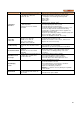
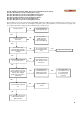
Sensor Not
Connected
• Inlet sensor, Alert: 91
• Outlet sensor, Alert: 92
• DHW sensor, Alert: 93
• Flue sensor, Alert: 95
• Outdoor sensor, Alert: 96
• Verify that the sensors are connected
• Verify that they are wired correctly.
• Measure the resistance of the sensors, 10kΩ sensors.
• Replace the sensor if necessary
Fan Not Turning
• Fan refuses to rotate
• Alert 122, 123, 128, 129, 130,131,
132
• Check fan power wires
• Fan signal wires are interchanged
• Minimum fan speed must be greater than 1500 RPM
Blocked Flue Switch
• Check gas pressure switches, if
equipped
• Alert 63, 67, 79, 137, 276-281
•
I
LK
OFF
• Blocked flue switch wire(s) is/are loose
• Blocked flue switch is set too light if it trips at full fan
speed, reduce sensitivity by turning screw 1 turn
clockwise.
Flame Detection is
out of Sync
• Flame detection is present when no
visible signs of a flame exist
• Lockout 105, 158
• Verify supply voltage for proper polarity.
• Check external wiring for voltage feedback
• Check internal wiring for proper connections
• Check the flame sensor and verify that it is clean
• Replace DynaMax HS Controller
Blank Display
Screen
• Blank display screen • Check S4 switch position on ignition module. Switch is
pushed towards J5 connector
• Check that display is connected to the standalone
connector on the back of the display
Replace fuse with factory 3.15A fuse.
• DO NOT use alternates as it may damage the DynaMax
HS
Controller
Internal Fault
• Alert 3-9, 20-31
• Lockout 10-18, 32-46, 58-60 ,97-
99, 143
-
148
• Reset SOLA
• If fault persists, replace SOLA