
Service manual

64
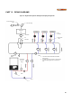
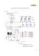
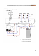
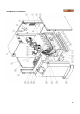
Figure 35: Multiple Boiler Hydronic Heating Zoned Piping Arrangement
Pressure Reducing
Valve
Pressure Gauge
Air
Separator
Expansion
Tank
Ball Valve
Zone
Circulator
Flow Check
Valve
DynaMax HS
Boiler
(Master, M1)
Temperature/
Pressure
Gauge
Drain
Union
DynaMax HS
Boiler
(Slave, S2)
System
Sensor
Note:
1) Size main header to minimize induced flow
through zones
2) Location of system sensor is based on single
speed building circulator. If a variable speed
building circulator is used, the system sensor
must be placed in the building supply.