DynaFlame/DynaForce BMS Protocol (Modbus, Bacnet IP, Bacnet MSTP, LONWorks, Metasys N2) Installation Guide 93-0238 Rev. 3.
DynaFlame/DynaForce SOLA and BMS Protocols Table of Contents 1.1 1.2 1.3 1.5 1.6 1.7 1.8 1.10 1.11 1.12 Bacnet/LONWorks/Metasys N2Setup through Protocessor Protonode RER/LER .............. 3 Protonode RER and LER showing connection ports .......................................................... 3 Record Identification Data ............................................................................................... 3 Connection from DynaFlame/DynaForce to ProtoNode .....................................
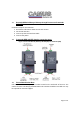
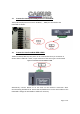
1.1 Bacnet/LONWorks/Metasys N2Setup through Protocessor Protonode RER/LER Installation steps for the customer 1. Record the information about the unit See Section 2. Set the DIP switches 3. Connect up the Field and Host cable 4. Connect the power 1.2 Protonode RER and LER showing connection ports Figure 1: Protonode Bacnet/ Metasys N2 RER (left) and Lonworks (LER) 1.3 Record Identification Data Each ProtoNode has a unique part number located on the underside of the unit.
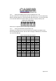
1.4 Configure the DIP Switches 1.4.1 Setting the Protocol that is required on site. Selecting the required Protocol To configure the Protonode to match what is on site please follow the below chart identifying the dipswitch settings for the different configurations. For example, if the BMS requires communication over Bacnet IP and there are four boilers on site the technician would select Bacnet IP 4 Sola and configure the S0 – S3 dipswitches on the ProtoCarrier accordingly.
FPC-N34-103-122-0565 Dipswitch settings S0 Off On Off On Off On Off On Off On Off On Off On Off On Off On Off On Off On Off On ProtoCarrier Dipswitches S1 S2 Off Off Off Off On Off On Off Off On Off On On On On On Off Off Off Off On Off On Off Off On Off On On On On On Off Off Off Off On Off On Off Off On Off On On On On On S3 Off Off Off Off Off Off Off Off On On On On On On On On Off Off Off Off Off Off Off Off A1 A2 ProtoCessor Dipswitches A3 A4 A5 A6 A7 A8 Refer to 1.4.
1.4.2 Setting the Node/ID Device Instance (Dipswitch A0 – A7) The DIP switches on the ProtoNode RER and LER allow users to set the Baud Rate, Node-ID and Mac address on the Field RS-485. Dip switches A0 – A7 can also be used to set the MAC Address for BACnet MSTP. This does not apply to Metasys N2. Figure 2: A0 – A7 Dip Switches Please refer to Appendix A for the full range of addresses. 1.4.
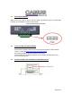
1.5 Connection from DynaFlame/DynaForce to ProtoNode The DynaFlame/DynaForce terminals J3-MB2 (+, -, GND) are connected to the ProtoNode as shown. 1.6 Connection from ProtoNode RER to BMS The Bacnet MSTP/ Metasys N2 system can be connected to the 3-pin connector as shown. When LonWorks is used, a 2-pin connector of the same type is used instead. Figure 3: Connection from ProtoNode to BMS Alternatively connect Bacnet IP to the hub via the Ethernet connection when communicating with Bacnet IP.
1.7 Power Up the Device Apply power to the device. Ensure that the cable is grounded using the “Frame-GND” terminal. The ProtoNode is factory set for 24Vac. Figure 4: Supply Voltage to ProtoNode 1.8 Install and Run the Utility Software - 1.9 Download the RUINET Utilities from the Protocessor web site (under Utilities section – Install.zip) www.protocessor.com/downloads/ Run Install.
- - Disable any wireless Ethernet adapters on the PC/Laptop Disable firewall and virus protection software Connect an Ethernet cross-over cable between the PC and ProtoNode and the PC to the Hub/Switch using a straight cat5 cable The Default IP Address of the ProtoNode is 192.168.1.24, Subnet Mask is 255.255.255.0. If the PC and the ProtoNode are on different IP Networks, assign a static IP Address to the PC on the 192.168.1.0 network. Double click on the “RUIPING” Utility.
1.10 - Connect to the ProtoNode using RUI (Ruinet) Double click on the debugging utility, “RUINET” (Remote User Interface). The following screen will appear: (if Ruinet does not automatically display the main menu, select the ProtoNode by typing the 2-digit number to the left of the title name). Figure 7: RUINET screen - - - - Select “O” for Connection Overview to see the number of messages on each protocol.
1.10.1 Changing the Modbus Address o Change the Modbus Address on the DynaFlame/DynaForce SOLA Go to [Configure] Go to System Identification & Access Change the Modbus address to the desired setpoint and press [OK] o Open up the .
1.11 Troubleshooting Tips Connection to the ProtoNode - Confirm that the network cabling is correct - Confirm that the computer network card is operational and correctly configured - Confirm that there is an Ethernet adapter installed in the PC’s Device Manager List, and that it is configured to run the TCP/IP protocol. - Check that the IP netmask of the PC matches the ProtoNode. The Default IP Address of the ProtoNode is 192.168.1.24, Subnet Mask is 255.255.255.
No communication with BMS.
1.
Light PWR SYS ERR COMM ERR Config ERR Node Offline Unused RX TX RUN Description This is the power light and should show steady green at all times when the FPC-FD2 is powered. The SYS ERR LED will go on solid 15 seconds after power up. It will turn off after 5 seconds. A steady red light will indicate there is a system error on the ProtoCessor. If this occurs, immediately report the related “system error” shown in the error screen of the RUI interface to FieldServer Technologies for evaluation.
LonWorks Protocol Gateway LON PWR GP105 Rx Tx LA Light Description This is the power light and should show steady green at all times when the FFP-F04 is powered. Starts flashing about once per second to indicate that the PIC in the ProtoCessor has LA-PIC A powered up successfully Will go on solid within 45 – 60 seconds after power up, signifying normal operation. The GP105 ProtoCessor will be able to access RUINET shortly after this LED comes on. During the first 45-60 seconds the LED should be dark.
ProtoCarrier 485 (FPC-CD2) RS-485 Signal LEDs The RS-485 Signal LEDS are each labeled and correspond to the respective data lines sent from the ProtoCessor. The following signals are provided. RS-485 TX and RS-485 RX. 2.1 Modbus The DynaFlame/DynaForce is equipped with a standard ICP Modbus port through a 3-pin connector that interfaces to the following RS-485 signals: Table 3: Connection Terminals Signal Terminal Data + (a) 1 Data – (b) 2 Serial transmission mode on the Modbus network is RTU mode.
2.
Outlet Sensor Firing Rate Fan Speed Flame Signal Inlet Sensor DHW Sensor S5 Sensor Stack Sensor 4-20mA remote control input Active CH Setpoint Active DHW Setpoint Active Lead Lag (LL) Setpoint Analog modulation input Burner Control Status 0007 0007 AI/AI 3 2 R 11 = Warm weather shutdown -40 – 130oC (0.
Lockout Code Alarm Reason 0022 0034 AI/AI 17 16 R 0023 0035 AI/AI 18 17 R Annunciator first out 0024 0036 AI/AI 19 18 R Annunciator hold 0025 0037 AI/AI 20 19 R Hold code Remote Stat CH Status 0028 002A 0040 0040 0042 0064 AI/AI AI/AI AI/AI 21 22 23 20 21 22 R R/W R 35 = Standby delay 36-47 = Reserved 48 = Normal standby 49 = Preparing 50 = Ignition 51 = Firing 52 = Postpurge 53-65535 = Reserved 0 = No lockout 1 – 4096 (See Table 4) 0 = None 1 = Lockout, see register (hex)
CH Setpoint Source 0041 0065 AI/AI 24 23 R CH Heat Demand CH Burner Demand CH Requested Rate DHW Status 0042 0066 AI/AI 25 24 R 0043 0067 AI/AI 26 25 R 0044 0068 AI/AI 27 26 R 0050 0080 AI/AI 28 27 R DHW Heat Demand DHW Burner Demand DHW Requested Rate 0053 0083 AI/AI 29 28 R 0054 0084 AI/AI 30 29 R 0055 0085 AI/AI 31 30 R 1 = Disabled 2 = Normal 3 = Suspended 0 = Unknown 1 = Normal Setpoint 2 = Time of Day Setpoint 3 = Outdoor reset 4 = Remote control 7 =
Bitmap 15 – 14 = Reserved 13 = Auxiliary 2 pump demand 12 = Auxiliary 1 pump demand 11 = System pump demand 10 = Boiler pump demand 9 = DHW pump demand 8 = CH pump demand Reason 7 = Reserved 6 = Pump assigned to logical pump 5 = Pump exercise requested 4 = Pump on due to exercise 3 = Pump on due to Post pump 2 = Forced off 1 = Forced on 0 = On due to normal demand Application Build < 1600 Application Build > 1600 Pump A Status 005D 0093 AI/AI 32 31 R Pump B Status 005E 0094 AI/AI 33 32 R CH p
Cycle Count DHW Pump Cycle Count System Pump Cycle Count Boiler Pump Cycle Count Controller Run Time Lead Lag Master Status 0086-0087 0134-0135 AV/AO 92 4 R/W 0-999,999 0088-0089 0136-0137 AV/AO 93 5 R/W 0-999,999 008A-008B 0138-0139 AV/AO 94 5 R/W 0-999,999 0090-0091 0144-0145 AI/AI 95 7 R 0-999,999 hours 00A0 0160 AI/AI 38 37 R Lead Lag Slave Status 00A1 0161 AI/AI 39 38 R Pump C Status 00A8 0168 AI/AI 40 39 R 0 = Unknown 1 = Disabled 2 = Normal 3 = Suspend
40 R 11 = System pump demand 10 = Boiler pump demand 9 = DHW pump demand 8 = CH pump demand Reason 7 = Reserved 6 = Pump assigned to logical pump 5 = Pump exercise requested 4 = Pump on due to exercise 3 = Pump on due to Post pump 2 = Forced off 1 = Forced on 0 = On due to normal demand -40 – 130oC (0.
R/W 1 = On 0 = Disable Central Heating 1 = Enable Central Heating -40 – 130oC (0.1oC precision)1 -40 – 130oC (0.1oC precision)1.
DHW Frost Protection Enable 0211 0529 AV/AO 61 R/W 0 = Disable 1 = Enable Outdoor Frost Protection Setpoint Lead Lag Slave Enable 0212 0530 AV/AO 62 R/W -40 – 130oC (0.
Slave Command 0235 0565 AV/AO 98(Boiler Firing Rate using percentage), 99 (Boiler Firing Rate using Binary), 100 (Boiler Enable) R/W CH Modbus Setpoint CH Modulation Rate Source CH Modbus Rate Warm Weather Shutdown Setpoint Lead Lag DHW Setpoint Slave 1 State Slave 2 State Slave 3 State Slave 4 State Slave 5 State 0243 0579 AV/AO 68 R/W Bitmap 15 = Slave demand request 14 = Slave suspend startup 13 = Slave run fan request 12 = Turn on auxiliary pump X 11 = Turn on auxiliary pump Y 10 = Turn on a
Slave 6 State Slave 7 State Slave 8 State 0316 031A 031E 0790 0794 0798 AI/AI AI/AI AI/AI 83 85 87 82 84 86 R R R Slave 1 Firing Rate Slave 2 Firing Rate Slave 3 Firing Rate Slave 4 Firing Rate Slave 5 Firing Rate Slave 6 Firing Rate Slave 7 Firing Rate Slave 8 Firing Rate Lead Boiler Address 0304 0772 AI/AI 74 R 0308 0776 AI/AI 76 R 030C 0780 AI/AI 78 R 0310 0784 AI/AI 80 R 0314 0788 AI/AI 82 R 0318 0792 AI/AI 84 R 031C 0796 AI/AI 86 R 0320 0800 AI/AI 88 R 03
All temperature registers are expressed in oC regardless of what temperature units are set to on the boiler, ex. 32.0oC = 320. A temperature that is NOT applicable has a value of 0x8FFF. 2 All percentage values are given in 0.1% granularity, ie. 0-1000 is the range from 0.0 – 100.0% 3 Most significant bit in value determines which units type the parameter has: 0 = RPM, 1 = %.
2.
38 39 40 41 42 43 44 45 46 47 48 49 50 51 52 53 54 55 56-57 58 59 60 61 62 63 67 68 69 70 71-77 78 79 81 82 91 92 93 94 95 96 97 98 99 101-104 Internal fault: Safety key 6 Internal fault: Safety key 7 Internal fault: Safety key 8 Internal fault: Safety key 9 Internal fault: Safety key 10 Internal fault: Safety key 11 Internal fault: Safety key 12 Internal fault: Safety key 13 Internal fault: Safety key 14 Flame rod to ground leakage Static flame (not flickering) 24Vac voltage low/high Modulation fault Pump
105 106 107 108 109 110 111 112 113 114-121 122 123 124 125 126 127 128 129 130 131 132 133-135 136 137 138-142 143 144 145 146 147 148 149 150 151 158 159 160 161 162 163 166-171 172 173 174 Flame detected out of sequence Flame lost in MFEP Flame lost early in run Flame lost in run Ignition failed Ignition failure occurred Flame current lower than WEAK threshold Pilot test flame timeout Flame circuit timeout RESERVED Lightoff rate proving failed Purge rate proving failed High fire switch OFF High fire swi
175 176 177 178 179-183 184 185 186 187 188 189 192 193 194 195 196 197 198 199 200 201 202 203 204 205 206 207 208 209 210 211 212 213 214 215 216 217 218 219 224 225 226 228 229 Safety relay open Main relay ON and safe start check Pilot relay ON at safe start check Safety relay ON at safe start check RESERVED Invalid Blower/HIS output setting Invalid Delta T limit enable setting Invalid Delta T limit response setting Invalid DHW high limit enable setting Invalid DHW high limit response setting Invalid Fl
230 231 234 235 236 237 238 239 240 244 246 250 252-255 2.
21 22 23 24 25 26 27 28 29 30 31 32 33 34 35 36 37 38 39 40 41 42 43 44 45 46 47 48 49 50 51 52 53 54 55 56 57 58 59 60 61 62 63 64 65 66 67 68 69 Invalid safety group verification table was not accepted CRC errors were found in application configuration data blocks Backup Alert PCB was restored from active one RESERVED Lead Lag operation switch was turned OFF Lead Lag operation switch was turned ON Safety processor was reset Application processor was reset Burner switch was turned OFF Burner switch was tu
70 71 7273 74 75 76 77 78 79 80 81 8283 84 85 86 87 88 89 90 91 92 93 94 95 96 97 98 99 100 101 102 103 104 105 106 107 108 109 110 111 112 113 114 115 116 117 118 119 120 121 No demand source was set due to demand priority conflicts CH 4-20mA signal was invalid RESERVED Periodic Forced Recycle Absolute max fan speed was out of range Absolute min fan speed was out of range Fan gain down was invalid Fan gain up was invalid Fan minimum duty cycle was invalid Fan pulses per revolution was invalid Fan PWM freq
122 123 124 125 126 127 128 129 130 131 132 133 134 135 136 137 138 139 140 141 142 143 144 145 146 147 148 149 150 151 152 153 154 155 156 157 158 159 160 161 162 163 164 165 166 167 168 169 170 171 Modulation commanded rate was < min modulation rate Modulation rate was limited due to Outlet limit Modulation rate was limited due to Delta-T limit Modulation rate was limited due to Stack limit Modulation rate was limited due to anticondensation Fan speed out of range in RUN Modulation rate was limited due t
172 173 174 175 176 177 178 179 180 181 182 183 184 185 186 187 188 189 190 191 192 193 194 195 196 197 198 199 200 201 202 203 204 205 206 207 208 209 210 211 212 213 214 215 216 217 218 219 220 221 DHW temperature was invalid DHW inlet temperature was invalid DHW outlet temperature was invalid DHW high limit must be disabled for Auto mode DHW sensor type was not compatible for Auto mode DHW priority source setting was invalid DHW priority method setting was invalid CH S5 (J8-11) sensor was invalid CH Inl
222 223 224 225-226 227 228 229 230 231 232 233 234 235 236 237 238 239 240 241 242 243 244 245 246 247 248 249 250 251 252 253 254 255 256 257 258 259 260 261 262 263 264 265-266 267 268 269 270 271 272 273 CH frost protection temperature was invalid CH frost protection inlet temperature was invalid DHW frost protection temperature was invalid RESERVED DHW priority override time was not derated due to invalid outdoor temperature Warm weather shutdown was not checked due to invalid outdoor temperature Lead
274 275 276 277 278 279 280 281 282 283 284 285 286 287 288 289 290 291 292 293 294 295 296 297 298 299 300 301 302 303 304 305 306 307 308 309 310 311 312 313 314 315 316 317 318 319 320 321 322 323 Abnormal Recycle: Demand off during Pilot Flame Establishing Period Abnormal Recycle: LCI off during Drive to Purge Rate Abnormal Recycle: LCI off during Measured Purge Time Abnormal Recycle: LCI off during Drive to Lightoff Rate Abnormal Recycle: LCI off during Pre-Ignition test Abnormal Recycle: LCI off duri
324 325 326 327 328 329 330 331 332 333 334 335 336 337 338 339 340 341 342 343 344 345 346 347 348 349 350 351 352 353 354 355 356 357 358 359 360 361 362 363 364 365 366 367 368 369 370 371 372 373 Abnormal Recycle: Hardware flame bias Abnormal Recycle: Hardware static flame Abnormal Recycle: Hardware flame current invalid Abnormal Recycle: Hardware flame rod short Abnormal Recycle: Hardware invalid power Abnormal Recycle: Hardware invalid AC line Abnormal Recycle: Hardware SLO flame ripple Abnormal Recy
374 375 376 377 378 379 380 381 382 383-450 451 452 453 454 455 456 457 458 459 460 461 462 463 464 465 466 467 468 469 470 471 472 473 474 475 476 477 478 479 480 481 482 483 484 485 486 487 488 489 490 Abnormal Recycle: Hardware flame bias high Abnormal Recycle: Hardware flame bias low Abnormal Recycle: Hardware flame bias delta high Abnormal Recycle: Hardware flame bias delta low Abnormal Recycle: Hardware flame bias dynamic high Abnormal Recycle: Hardware flame bias dynamic low Abnormal Recycle: Fan Sp
491 492 493 494 495 496 497 498 499 500 501 502 503 504 505 506 507 508 509 510 511 512 513 514 515 516 517 518 519 520 521 522 523 524 525 526 527 528 529 530 531 532 533-539 540 541 542 543 545 546 547 Internal error: Safety key bit 13 was incorrect Internal error: Safety key bit 14 was incorrect Internal error: Safety key bit 15 was incorrect Internal error: Safety relay timeout Internal error: Safety relay commanded off Internal error: Unknown safety error occurred Internal error: Safety timer was corr
548 549 550 551 552 553 554 555 556 557 558 559 560 561 562 563 564 565 566 567 568 569 570 571 572 573 574 575 576 577 578 579 580 581 582-589 590 591 592 593 594 595 596 597 598 599 600 601 602 603 604 Delta T rate limit enable was invalid Delta T exchanger/outlet wasn't allowed due to stack limit setting Delta T inlet/outlet limit was exceeded Delta T exchanger/outlet limit was exceeded Delta T inlet/exchanger limit was exceeded Inlet/outlet inversion occurred Exchanger/outlet inversion occurred Inlet/e
Appendix A A7 A6 A5 A4 A3 A2 A1 A0 Address Off Off Off Off Off Off Off Off Off Off Off Off Off Off Off Off Off Off Off Off Off Off Off Off Off Off Off Off Off Off Off Off Off Off Off Off Off Off Off Off Off Off Off Off Off Off Off Off Off Off Off Off Off Off Off Off Off Off Off Off Off Off Off Off Off Off Off Off Off Off Off Off Off Off Off Off Off Off Off Off Off Off Off Off Off Off Off Off Off Off Off Off Off Off Off Off Off Off Off Off Off Off Off Off Off Off Off Off Off Off Off Off Off Off Of
Off Off Off Off Off Off Off Off Off Off Off Off Off Off Off Off Off Off Off Off Off Off Off Off Off Off Off Off Off Off Off Off Off Off Off Off Off Off Off Off Off Off Off Off Off Off Off Off Off Off Off Off Off Off Off Off Off Off Off Off Off Off Off Off Off Off Off On On On On On On On On On On On On On On On On On On On On On On On On On On On On On On On On On On On On On On On On On On On On On On Off Off Off Off Off Off Off Off Off Off Off Off Off Off Off Off Off Off Off Off Off Off Off Off Off Off
Off Off Off Off Off Off Off Off Off Off Off Off Off Off Off Off Off Off Off Off Off Off Off Off Off Off Off Off Off Off Off Off Off Off Off Off Off Off Off On On On On On On On On On On On On On On On On On On On On On On On On On On On On On On On On On On On On On On On On On On On On On On Off Off Off Off Off Off Off Off Off Off Off Off Off Off On On On On On On On On On On On On On On On On On On On On On On On On On On On On On On On On Off Off Off Off Off Off Off On On On On On On On Off Off Off Of
On On On On On On On On On On On On On On On On On On On On On On On On On On On On On On On On On On On On On On On On On On On On On On Off Off Off Off Off Off Off Off Off Off Off Off Off Off Off Off Off Off Off Off Off Off Off Off Off Off Off Off Off Off Off Off Off Off Off Off Off Off Off Off Off Off Off Off Off Off Off Off Off Off Off Off Off Off Off Off Off Off Off Off Off Off Off Off Off Off Off Off Off Off Off On On On On On On On On On On On On On On On On On On On On On Off Off Off Off Off Off
On On On On On On On On On On On On On On On On On On On On On On On On On On On On On On On On On On On On On On On On On On On On On On Off Off Off Off Off Off Off Off Off Off Off On On On On On On On On On On On On On On On On On On On On On On On On On On On On On On On On On On On On On On On On On On On On On On Off Off Off Off Off Off Off Off Off Off Off Off Off Off Off Off Off Off Off Off Off Off Off Off Off Off Off Off Off Off Off Off On On On On On On On On On On On On On On Off Off Off Off Off
On On On On On On On On On On On On On On On On On On On On On On On On On On On On On On On On On On On On On On On On On On On On On On On On On On On On On On On On On On On On On On On On On On On On On On On On On On On On On On On On On On On On On On On Off Off Off Off Off Off Off Off Off Off Off Off Off On On On On On On On On On On On On On On On On Off Off Off Off Off On On On On On On On On Off Off Off Off Off Off Off Off On On On On On On On On Off On On On On Off Off Off Off On On On On Of
Page 51 of 51