INSTALLATION OPERATION AND SERVICE MANUAL MICOFLAME SERIES 2 GAS FIRED COMMERCIAL COPPER TUBE BOILERS FOR HYDRONIC HEATING Models; MFH800, 1000, 1200, 1400, 1600, 1800, 2000 HOT WATER SUPPLY Models; MFW800, 1000, 1200, 1400, 1600, 1800, 2000 H HLW WARNING: If the information in these instructions is not followed exactly, a fire or explosion may result causing property damage, personal injury or death • Do not store or use gasoline or other flammable vapours and liquids in the vicinity of this or any othe
Table of Contents INTRODUCTION ................................................................................................................................................... 1 1 GENERAL INSTRUCTIONS ............................................................................................................................ 1 2 BOILER LOCATION .......................................................................................................................................
20 LIGHTING INSTRUCTIONS .......................................................................................................................... 35 21 TROUBLE SHOOTING GUIDE...................................................................................................................... 36 22 TYPICAL GAS TRAIN ................................................................................................................................... 37 23 ELECTRICAL DIAGRAMS ...................................
INTRODUCTION Camus Hydronics proudly introduces its MicoFlame series 2 of commercial water heaters / hydronic boilers. These gas-burning appliances are thoughtfully designed for easy operation and maintenance. We are confident that you will come to appreciate the benefits of our product.
2 BOILER LOCATION Install this boiler in a clean, dry location with adequate air supply and close to a good vent connection. Do not locate this boiler in an area where it will be subject to freezing. The boiler is suitable for installation on combustible flooring and should be located close to a floor drain in an area where leakage from the boiler or connections will not result in damage to the adjacent area or to lower floors in the structure.
Table 2: Various Connection Sizes B' Dia. Venting* 8 8 10 10 12 12 12 8 8 10 10 12 12 12 Air Inlet 1 1 1/4 1 1/4 1 1/4 1 1/2 1 1/2 1 1/2 Standard Condensing or Sidewall Outdoor 2 1/2 2 1/2 2 1/2 2 1/2 2 1/2 2 1/2 2 1/2 Gas Connection W' 45 3/4 52 3/4 62 71 1/4 80 3/4 89 3/4 99 Water Connection Model MF800 MF1000 MF1200 MF1400 MF1600 MF1800 MF2000 E' Dia.
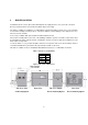
5 STAGING OPERATION Staging of the MicoFlame series 2 is dependent on the number of burners supplied. Models 800 and 1000 are supplied with a single burner and are available as on/off and two stages. Models 1200 through 2000 are supplied with two burners and are available as on/off, 2-stage, 3-stage and 4-stage. Each burner is supplied with a dedicated airflow proving signal and separate proved pilot ignition system. All fans must be running in order for the appliance to proceed to trial for ignition.
6 GAS SUPPLY AND PIPING This boiler is intended to operate at inlet gas pressures not exceeding ½ PSI (14“ W.C.). If higher pressures are present, consult the gas company for correction. When pressure testing the gas supply piping at pressures above ½ PSI, the boiler and its individual gas shut-off valve must be disconnected from the supply piping. Provide a trap (drip leg) as close to the heater as possible.
When an existing boiler is removed from a common venting system, the common venting system is likely to be too large for proper venting of the appliances remaining connected to it. At the time of removal of an existing boiler, the following steps must be followed with each appliance remaining connected to the common venting system placed in operation, while the other appliances remaining connected to the common venting system are not in operation. a) Seal any unused openings in the common venting system.
8. While the boiler is operating, check for flue gas leaks and proper vent operation. Seal any flue gas leaks using appropriate gasket or sealing material. Carefully examine the flue collector access panel and heat exchanger ends. The MicoFlame series 2 is category 1, 85% efficient when supplied as a non-condensing appliance. When supplied with the optional condensing cartridge, the MicoFlame series 2 is 95% efficient and is considered to be a category II or IV appliance.
7.2 SIDEWALL VENTING When fitted with the factory supplied vent terminal, the MicoFlame series 2 can vent up to 60 equivalent feet. Elbows can range from 8 to 15 feet in equivalent length depending on centreline radius. See Table 1 for vent sizes. Boilers may be installed with either a horizontal sidewall vent or vertical roof top terminal. Terminals differ with each application. Horizontal lengths over 5 feet must be installed using corrosion resistant stainless steel.
7.4 FILTER KIT A louvered rear panel is the standard air inlet configuration for the MicoFlame series 2. A filter kit is available. The filter is washable and accounts for an additional pressure loss of less than 0.05” W.C. Highly recommended for dusty environments. The filter kit can also be provided when using the outdoor air kit. 7.5 STANDARD VENTING The MicoFlame series 2 is a category 1 appliance and is approved for venting into a common standard chimney.
RELIEF VALVE (shipped loose) This appliance is supplied with a relief valve sized in accordance with ASME Boiler and Pressure Vessel Code, Section IV (“Heating Boilers”). The relief valve is to be installed in the vertical position and mounted in the hot water outlet. No valve is to be placed between the relief valve, and the appliance. To prevent water damage, the discharge from the relief valve shall be piped to a suitable floor drain for disposal when relief occurs.
9 FREEZE PROTECTION • Appliance installations are not recommended outdoors in areas where danger of freezing exists unless precautions are taken. Maintaining a mixture of 50% water and 50% propylene glycol is the preferred method of freeze protection in hydronic systems. This mixture will protect the appliance to approximately -35ºF (-37ºC). To maintain the same temperature rise across the appliance increase the GPM flow by 15% and the head loss by 20%.
11 PIPING OF BOILER TO SYSTEM (FIG.5) Check all applicable local heating, plumbing and building safety codes before proceeding. Be sure to provide unions and gate valves at inlet and outlet to boiler so that it can be easily isolated for service. This boiler is of a low mass design, which provides for instant heat transfer. Special attention to water flow rates will ensure that temperature rise does not exceed 35°F (19.4°C). The following table is provided as a guide.
If the boiler is installed above radiation level, it must be provided with a low water cutoff device at the time of boiler installation. (Available from factory) To eliminate trapped air, install venting devices at high points in the system as well as in the piping on the suction of the pump and in the piping on the discharge of the boiler. Suitable pipe hangers must support the weight of all water and gas piping or floor stands.
Figure 6 – Display, Appliance Temperature Controller and Indicating LED The Boiler Temperature Controller (BTC) for this appliance is a Camus 780014 SmartFlame control. This controller accommodates up to four-stage control with six modes of operation which provides setpoint as well as rest control. It provides the following: 1. Readings of inlet and outlet water temperatures as well as ∆T temperature rise. 2.
KEY Item KEY DESCRIPTION The abbreviated name of the selected item will be displayed in the item field of the display. To view the next item, press the Item button. Increase a parameter value. Decrease a parameter value. Levels of Access View – Access to general boiler and display settings and will allow adjustments to the central heating and domestic hot water setpoint.
13.2.1 MODE 1 & 2: SETPOINT OPERATION Mode 1 Intended for hydronic heating. The set-point for inlet water control is pre-set to 180°F and the auto re-set limit is set to 230°F. The inlet set-point can be a djusted, however the limit is fixed. In addition to the auto reset limit the factory installs a manual re-set limit set to 250°F.
13.2.
13.2.3 MODE 1 & 2: SETPOINT OPERATION: ADJUST DISPLAY From the Home display; 1) Press simultaneously to view the following parameters: Parameter Display Parameter Description Name Parameter Range 1 to 6 Mode Operating mode for the boiler. Default = 1 o Boiler Target Temperature To provide a target setpoint for the heating system. Setpoint is controlled to the inlet sensor Boil Mass (Mode 2 ONLY) Thermal mass of boiler. This determines interstage delay and minimum on and minimum off times.
13.2.4 MODE 3: DHW SETPOINT OPERATION Mode 3 is intended for domestic water heating. The set-point for inlet water control is pre-set to 140°F and the auto re-set limit is set to 200°F. The inle t set-point can be adjusted, however the limit is fixed. In addition to the auto reset limit the factory installs a manual re-set limit set to 210°F. The control turns on the appliance pump and stages the appliance to maintain set-point target temperature at the appliance inlet temperature.
13.2.6 MODE 3: DHW SETPOINT OPERATION: ADJUST DISPLAY From the Home display; 1) Press simultaneously to view the following parameters: Display Parameter Name Parameter Description Parameter Range 1 to 6 Mode Operating mode for the boiler. Default = 1 o Boiler Target Temperature To provide a target setpoint for the heating system.
13.2.7 MODE 4 & 5: OUTDOOR RESET OPERATION Mode 4 is intended for hydronic heating. The set-point for inlet water control is pre-set to 180°F and the auto re-set limit is set to 230°F. The inlet set-po int can be adjusted, however the limit is fixed. In addition to the auto reset limit the factory installs a manual re-set limit set to 250°F.
13.2.
13.2.9 MODE 4 & 5: OUTDOOR RESET OPERATION: ADJUST DISPLAY From the Home display; 1) Press simultaneously to view the following parameters: Display Parameter Name Parameter Description Parameter Range 1 to 6 Mode Operating mode for the boiler. Default = 1 o Outdoor Start Temperature Outdoor starting temperature used in the reset ratio for the heating system. Typically set to the desired building temperature.
Pump Delay Boiler post pump time after burner has shut off, in seconds. OFF, 0:20 to 9:55 min, On Default = 1:00 min Warm Weather Shutdown Temperature o Warm weather shutdown temperature using outdoor reset. 35 to 105 F, OFF o (2 to 41 C, OFF) Default = 0:20 min o Temperature Units o F, C Select the desired unit of measurement 13.2.10 MODE 6: EXTERNAL TARGET TEMPERATURE USING BOILER INLET SENSOR The external input signal can be provided from a BMS, EMS or a Tekmar tN4 System Control.
13.2.11 MODE 7: EXTERNAL TARGET TEMPERATURE USING SYSTEM TEMPERATURE SENSOR The external input signal can be provided from a BMS, EMS or a Tekmar tN4 System Control. The external input signal creates an internal demand and changes the boiler target according to a linear scale. The control modulates the boiler to maintain the boiler target at the outlet sensor.
13.2.12 MODE 6 & 7: EXTERNAL TARGET TEMPERATURE INPUT OPERATION: VIEW DISPLAY From the Home display; 1) Press [ITEM] to view the following parameters: Display Parameter Name Parameter Description Parameter Range Boiler Target Temperature To provide a target setpoint for the heating system. Setpoint is controlled to the inlet sensor.
13.2.13 MODE 6 & 7: EXTERNAL TARGET TEMPERATURE INPUT OPERATION: ADJUST DISPLAY From the Home display; 1) Press simultaneously to view the following parameters: Display Parameter Name Parameter Description Parameter Range Operating mode for the boiler. NOTE: A complete description of each mode can be found in section 6.1 Modes of Operation in this manual. Mode Modulation Mode Modulation mode.
Display Parameter Name Parameter Description Minimum Modulation Selects the minimum modulation rate Maximum Modulation Selects the maximum modulation rate Differential Temperature To provide a modulation rate above and below the Boiler Target temperature. For example, o if the value is 10 F and the Boiler o Target is 160 F the boiler will o begin to modulate at 155 F and o shut off at 165 F. Pump Delay Boiler post pump time after burner has shut off, in seconds.
14 4-20 mA Boiler Target 0-10V (dc)* 0 - - - (OFF) 0 2 - - - (OFF) 1 50 F (10 C) 4 50 F (10 C) 6 70 F (21 C) 8 90 F (32 C) 10 110 F (43 C) 12 130 F (54 C) Boiler Target - - - (OFF) o o o o o o o o 2 68 F (20 C) o o 3 86 F (30 C) o o 4 103 F (39 C) o o o o o o o o o o o o o o o o 5 121 F (49 C) o o 6 139 F (59 C) o o 7 157 F (69 C) o o 8 174 F (79 C) o o 9 192 F (89 C) o o 10 210 F (99 C) 14 150 F (66 C) 16 170 F (77 C) 18 190
• Adjustment procedure. a. Fully open bypass and outlet valves. b. With boiler running, read inlet temperature after 15 minutes. c. If the inlet temperature is less than 110°F slow ly close outlet valve until the inlet temperature climbs to 110°F d. If the inlet temperature is greater than 110°F b ut not greater than 140°F no further adjustment is required. e. Check the inlet temperature after 5 minutes and make final adjustments.
31
18 PILOT AND MAIN BURNER FLAMES To maintain safe operation and the greatest efficiency of the boiler, check the main burner and pilot burner every six months for proper flame characteristics. 18.1 MAIN BURNER The main burner, Figure 9 should display the following characteristics; • Acceptable CO and CO2 levels for complete combustion. • Light off smoothly. • Reasonably quiet while running. • Stable flame with minimum of lifting.
1. Shut off power and close main manual gas valve. • Allow burner to cool before removal. 2. Remove access cover screws. • Disconnect pilot gas at bulkhead fitting. • Disconnect ground wire and ignition wire. • Remove two wing nuts holding down burner. • Gently pull down and forward to disengage burner. • Remove burner being careful to not damage the igniter or ground electrodes. 3. Thoroughly clean burner. Check all ports and air channels for blockage. 4.
18.2 PILOT BURNER Turn the pilot firing valve to off position and allow the boiler to try for ignition. Observe the spark making sure that it is strong and continuous. If the spark is not acceptable the igniter will have to be adjusted. This can be readily accomplished after removing the main burner. The spark gap should be 1/8” to 3/16” between igniter and ground rod and 3/8” between igniter and surface of metal fiber. Make sure that the electrode does not appear overheated or fouled with carbon.
19 OPERATION AND SERVICE OPERATION: Before operating the boiler, the entire system must be filled with water, purged of air and checked for leaks. Do not use Stop leak or other boiler compounds. The gas piping must also be leak tested. Any safety devices including low water cutoff, flow switch and high limit used in with this boiler must receive periodic inspection (every six months) to assure proper operation. A low water cutoff of the float type should be flushed every six months.
8. Open the main manual and main firing valves to allow gas to reach the main burner. If the main burner fails to ignite, turn the firing valve off and check to see that the pilot is burning. If not, repeat lighting procedure steps 1 thru 7. TO TURN OFF BOILER: Close main manual valve and main firing valve and turn off electric power to system. 21 TROUBLE SHOOTING GUIDE SYMPTOM 1. Power light is not lit when switch is flipped to “ON” 2. Water flow light remains off. 3. Pilot sparks but does not light 4.
22 TYPICAL GAS TRAIN Figure 11: Gas Train 23 ELECTRICAL DIAGRAMS Each MicoFlame series 2 boiler will be provided with its own wiring diagram to guarantee that any options ordered with the unit are properly detailed. The following diagrams 99-5072 and 99-5082 are provided as typical samples only.
38
39
Tekmar BTC-4PA Electrical Connections Terminal # 1 2 3 4 5 6 7 8 9 10 11 12 13 14 15 16 17 18 19 20 21 22 23 24 Label CD HtD Pr D Com Outdr Sys/D Boil O Boil in Com +Vdc -C Pmp Pmp Stg 1 Stg 1 Stg 2 Stg 2 Stg 3 Stg 3 Stg 4 Stg 4 Alarm R Tekmar BTC-4PA Description Unused Call for heat signal Proof Demand to signal pilot is active Common terminal for Outdoor, System and/or DHW sensors 10kΩ outdoor sensor 10kΩ system or DHW sensor 10kΩ boiler outlet sensor 10kΩ boiler inlet sensor Common terminal for boiler
24 EXPLODED VIEW 41
MicoFlame II Gas Train 42
MicoFlame II 800 – 1000 Control Box 43
25 MICO FLAME REPLACEMENT PARTS LIST MicoFlame II Model Size Item # Part Description 1 Combustion Chamber End Panel - Left 2 Combustion Chamber End Panel - Right 3 Combustion Chamber Rear Panel-Non Condensing Combustion Chamber Rear Panel-Condensing 800 1000 1200 1400 1600 1800 2000 14-4100 14-4101-08-10 14-4101-12-20 14-4102-08 14-4102-10 14-4102-12 14-4102-14 14-4102-16 14-4102-18 14-4102-20 14-4102-08-51 14-4102-10-51 14-4102-12-51 14-4102-14-51 14-4102-16-51 14-4102-18-51
MicoFlame II Model Size Item # 19 Part Description 800 1000 Combustion Chamber Support - Centre N/A Flue Collector Outlet-Non Condensing 14-4119-08-10 1200 1400 1600 1800 2000 14-4118-12-20 14-4119-12-16 14-4119-18-20 *20 Flue Collector Outlet-Condensing 14-4120-08-10-51 14-4120-12-20-51 21 Outer Jacket Side Panel - Right 14-4131 22 Outer Jacket Side Panel - Left 14-4132 23 Fan Mounting Support - Right 24 Fan Mounting Support - Left 25 Burner Door Stop 14-4134-08 14-4134-10 1
MicoFlame II Model Size Item # Part Description 800 1000 1200 1400 39 Return Header 15-5005 40 Header Bar 15-4157 41 Header Bar Stop (2 Required Per Unit) 14-4138 42 Control Panel Outer Cover 14-4171 43 Control Panel Outer Cover Door 14-4172 44 Blower Assembly 45 Ignition Module Continous S8610M3017 46 Ignition Module Single Try S8610043010 47 Refractory Set 48 Donut Gasket 49 Pre-Purge Card TTMOR24A1X7 50 30 Second Delay on Make 24-IMS24AaX30 51 Pump Delay Relay 52
MicoFlame II Model Size Item # 59 60 61 62 63 Part Description 800 1000 1200 1400 Ignitor Module (Continuous) S8610M3017 Ignitor Module (Single Try) S8600112010 Tekmar Controller (STG) Air Switch 115/24V AC Transformer 65 Mixing Tube (2 Required per Unit) Gas Valve (left) 1800 2000 BTC4PA IS3010106-5769A Low Gas Switch (Not Shown in Exploded View, in Boiler Price Book) High Gas Switch (Not Shown in Exploded View, in Boiler Price Book) 64 1600 C6097A1012 C6097B1028 HCT-01J28807 MF1-GMTM-0
WARRANTY GENERAL Camus Hydronics Limited (“Camus”), extends the following LIMITED WARRANTY to the owner of this appliance, provided that the product has been installed and operated in accordance with the Installation Manual provided with the equipment. Camus will furnish a replacement for, or at Camus option repair, any part that within the period specified below, shall fail in normal use and service at its original installation location due to any defect in workmanship, material or design.
CAMUS Hydronics is a manufacturer of replacement parts for most copper finned water heaters and heating boilers as well as a The CAMUS CERTIFIED! Seal assures you that Reliability, Efficiency & serviceability are built into every single unit! For more information supplier of specialty HVAC products. Our service line is open 24 hours, 7 days a week! on our innovative products from CAMUS Hydronics Limited, call 905-696-7800 today. CAMUS HYDRONICS LTD.