
Manual


This dual bidirectional motor driver is based on the very
popular L298 Dual H-Bridge Motor Driver Integrated Circuit.
The circuit will allow you to easily and independently control two
motors of up to 2A each in both directions.
It is ideal for robotic applications and well suited for
connection to a microcontroller requiring just a couple of control
lines per motor. It can also be interfaced with simple manual
switches, TTL logic gates, relays, etc.
The circuit incorporates 4 direction LEDs (2 per motor), a
heat sink, screw-terminals, as well as eight Schottky EMF-
protection diodes. Two high-power current sense resistors are
also incorporated which allow monitoring of the current drawn
on each motor through your microcontroller.
An onboard user-accessible 5V regulator is also
incorporated which can also be used to supply any additional
circuits requiring a regulated 5V DC supply of up to about 1A.
The circuit also offers a bridged mode of operation allowing
bidirectional control of a single motor of up to about 4A.
Manufacturer of High Quality Electronic Kits & Modules
Cana KitW
www.canakit.com
C
A
1
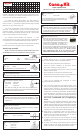
Resistors:
‚ R3, R4 1 KWBrown, Black, Red
‚ R5 470 WYellow, Violet, Brown
Refer to the General Assembly Guide included with the kit
for detailed instructions on installation of each component.
Step-by-step Assembly
2
Schottky Diodes:
‚ D1 – D8 FR107
* Note orientation of D1 – D4 are opposite of D5 – D8.
7
‚ Install the 10-pin right-angle header at its corresponding location.
Ceramic Capacitors:
‚ C3, C5 104 / 0.1 mF / 100nF
8
Electrolytic Capacitors:
‚ C1 100 mF / 50V
‚ C2, C6 10 mF / 50V
‚ C4 100 mF / 16V
‚ LED1, LED3 Yellow LED
‚ LED2, LED4 Red LED
‚ POW Green LED
Note that the anode (A) lead of the LED is longer than its
cathode (C) lead. Make sure you insert each LED lead through
the appropriate hole in the PC board.
4
Light Emitting Diodes (LEDs):
3
10-Pin Right Angle Header
L298 H-Bridge Dual Bidirectional
Motor Driver (2 x 2A)
CK1122
VERSION 1.0
5
3-Pin Jumper Header:
‚ Install the 3-pin jumper header at locations marked “J1”. Then
place the small plastic jumper head on the rightmost two pins
(position “A”).
6
2-pin Screw Terminals:
‚ Install the three 2-pin Screw Terminals at locations marked
“MOT1”, “MOT2” and “MOT DC”.
9
Power Resistors:
‚ R1, R2 0.5 W / 3 W
It is recommended to leave a space of about 1/8“
(3 mm) between the resistor and the PC board
for better heat dissipation.
10
11
5V Regulator Integrated Circuit:
L298 Integrated Circuit:
‚ Install the 7805 5V Regulator IC at location marked
“U2”. Make sure that the metallic side of the IC is lined
up with the outline on the board (the metallic part
should be facing towards “C4” electrolytic capacitor).
‚ Mount the L298 Integrated Circuit on the heat
sink using the short screw provided. Make
sure that you tightly fasten the heat sink to the
integrated circuit so that the maximum amount
of heat can be dissipated. If available, use a
small amount of Silicon Grease (also known as
Thermal Grease or Paste) between the heat sink and the L298
for even better heat dissipation. Then install the L298 with the
heat sink attached at location marked “U1”. Be very careful
when soldering the pins as to not cause any shorts
between the pins since they are very close to each other.
Before testing the kit, It is highly recommended to
inspect the PC board carefully as explained below:
‚ Check for proper placement of all components.
‚ Check for proper orientation of the LEDs, diodes,
electrolytic capacitors, and regulator IC.
‚ Check for protruding leads which could touch other
leads or adjacent pads.
‚ Check all solder connections for cold solder joints.
‚ Examine the PC board solder side to see that there are no
solder bridges causing shorts between tracks.
Once you are satisfied that everything is correct,
proceed to do the test as follows:
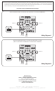
1. The circuit can be supplied in two different ways. Since
the circuit incorporates an onboard 5V DC regulator, the
required supply voltage for the operation of the L298
Integrated Circuit can be tapped off of the motor supply
voltage itself. Furthermore, this 5V DC regulated voltage
is also available for any other circuitry you may want to
drive. The jumper setting and wiring diagram for this way
of supplying the circuit is indicated in Wiring Diagram 1.
This is the recommended way of supplying the
circuit.
Alternatively, if you would like to keep the motor supply
voltage completely independent and isolated from the
L298 5V supply voltage, then you would need to provide
your own 5V DC regulated voltage to supply the L298 IC.
The jumper setting and wiring diagram for this way of
supplying the circuit is indicated in Wiring Diagram 2.
2. Each motor is controlled by setting to High “ENA” or
“ENB” for the corresponding motor. You can then control
the direction of each motor by enabling “IN1” or “IN2” for
motor “A” and “IN3” or “IN4” for motor “B”.
3. To “brake” a particular motor, you will need to set “ENA”
or “ENB” to High and then set both direction pins to either
High or Low.
4. To “coast” (i.e. let freely run) a particular motor, simply set
“ENA” or “ENB” to Low. When the enable of a particular
motor is set to Low, the corresponding motor “coasts”.
Testing