
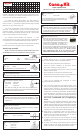
Manual

5. The circuit also incorporates two current sense outputs, “CSA” and “CSB” for each motor which expose the corresponding
current sense outputs of the L298 IC and incorporate the required high-power resistors. You can use these outputs to
monitor the current draw of each motor and detect stall conditions and take appropriate action. For more information on
how to use these, you may refer to the L298 Datasheet which can be found at:
http://www.canakit.com/Media/Datasheets/L298.pdf
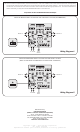
Wiring Diagram 1
Wiring Diagram 2
USING THE MOTOR SUPPLY VOLTAGE FOR THE L298 SUPPLY VOLTAGE (RECOMMENDED)
USING AN INDEPENDENT SUPPLY VOLTAGE FOR L298 SUPPLY VOLTAGE
(NOTE: IN THIS MODE THE ONBOARD 5V DC REGULATOR IS DISABLED)
5V DC
OUTPUT
6 – 35V DC
6 – 35V DC 5V DC
INPUT
MOTOR “A”
MOTOR “A”
MOTOR “B”
MOTOR “B”
J1
J1
Manufactured by:
Cana Kit Corporation
(Unikit is a division of Cana Kit Corporation)
#118 – 2455 Dollarton Highway
North Vancouver • BC • V7H 0A2 • Canada
Tel: (604) 298-3305 • Fax: (604) 298-3390
Email: info@canakit.com
Web Site: www.canakit.com
Copyright © 1990 – 2010 Cana Kit Corporation
All rights reserved
Reproduction without prior written permission is strictly prohibited