
Product Manual

M0112
8
TYPICAL INSTALLATIONS
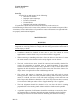
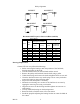
Wall exhaust fan with cabinet, back guard and shutter
The above drawing illustrates the typical installation of an exhaust fan with cabinet,
back guard and shutter in a masonry wall. The installer shall provide angle iron framing
and suitable fasteners (hex bolts or lag screws) to support the fan. The cabinet and
framing should be caulked to the exterior wall. Fans with motors in excess of 50
pounds should also be supported using hanging rods or by supports placed underneath
the fan.
ANGLE IRON
SUPPORTS
BY OTHERS.
A
WO
B
EXHAUST WALL FAN C/W CABINET, SHUTTER AND BACKGUARD
DDS,DDP,ADD
48 48
60
54
-
-
-
-
42
36
30
24
-
-
-
XB,HV,HVA
18
30
42
36
24
20
12
16
14
53 7/8
26*
54 7/8
59 7/8
+ For 15 hp and 20 hp add 8"
* For 7 1/2 hp and 10 hp add 6"
69
60 7/8
26*+
26*+ 68
47 7/8
41 7/8
35 7/8
29 7/8
24 1/4
22 1/4
20 1/4
18 1/4
16 1/4
23 1/4
36 7/8
48 7/8
42 7/8
30 7/8
25 1/4
17 1/4
21 1/4
19 1/4
WO
16
26
26*
26
26
16
16
16
16
A B
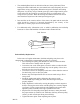
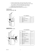
Wall supply fan with cabinet, back guard, motorized shutter and weather hood
The above drawing illustrates the typical installation of a supply fan with a cabinet,
back guard, motorized shutter (with end switch), and weather hood in a masonry wall.
The installer shall provide angle iron framing and suitable fasteners (hex bolts or lag
screws) to support the fan. The cabinet and framing should be caulked to the exterior
wall. The weather hood can either be attached to the cabinet or fastened to the wall and
then caulked. These fans should either be supported by hanging rods or by supports
placed underneath the fan.
ANGLE IRON
SUPPORT BY OTHERS
E
WO
A
B
D
C
Hood Free Area
ANGLE IRON SUPPORTS BY
OTHERS.