User manual and installation guide
Copyright 2012 Phason Inc. All rights reserved.
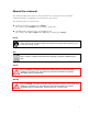
About the manual The manual describes the features of your TVS and how to use them; it does not describe ventilation strategies or equipment you can connect to the control. The following styles are in the manual. All buttons and menu commands are bolded. For example, "Press Program until the LED for Alarm is lit." All LED display examples are in a seven-segment font. For example, "Press Up or Down until a 20 displays and then press Select." Hint/tip This is a hint or tip.
How to use the manual If you are not sure where to find something specific, look in the Table of contents at the front of the manual or the Index on page 61. Below are some helpful suggestions. If you have not installed and configured your TVS, read Chapter 2: Installing your TVS on page 8 and Chapter 3: Configuring your TVS on page 23. If you are ready to install, configure, or program your TVS, use the worksheets starting in Appendix D on page 56.
Limited warranty This warranty applies only to the Phason Three Ventilation Stage Control (TVS). If you need warranty service, return the product and original proof of purchase to your dealer. Phason Inc. (Phason) warrants the TVS subject to the following terms and conditions. This warranty is valid only to the original purchaser of the product, for two years from the manufacturing date. The manufacturing date is stated in the first eight digits of the serial number in the form year-month-day.
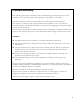
Service and technical support Phason will be happy to answer all technical questions that will help you use your TVS. Before contacting Phason, check the following: Read this manual for information about the feature with which you are having trouble. If you see an alarm message and are not sure what it means, look it up in the Alarm and error messages table on page 51 and then follow the instructions for resolving the alarm condition.
Table of contents Chapter 1: Introducing the TVS ...................................................................................................... 1 Introducing the TVS .................................................................................................................................. 1 Common applications........................................................................................................................... 1 Features ...................................................
Chapter 5: Monitoring and maintaining your TVS ....................................................................... 38 Monitoring your TVS ............................................................................................................................... 38 Displaying the minimum and maximum temperatures ....................................................................... 38 Selecting the operating program, parameter 0 .......................................................................
Chapter 1: Introducing the TVS Chapter 1 introduces you to the Three Ventilation Stage Control (TVS). Read chapter 1 before reading the rest of the manual. Topics in chapter 1 include: Introducing the TVS below Becoming familiar with the TVS on page 5 Introducing the TVS The TVS automatically controls the temperature in a room by operating two variable speed fans and a single-speed fan or heater.
Chapter 1: Introducing the TVS Phason Greenhouse applications Greenhouse applications include controlling ceiling louvers, variable and single-speed fans, and heaters. Business and light-industrial applications Business and light-industrial applications include machine shops, garages, and utility sheds where customers use the TVS to control fans and heaters. The TVS exhausts heat from the room made by equipment and/or regulates the temperature as service bays open and close.
TVS user manual Introducing the TVS Optional accessories Several optional, convenient accessories are available to enhance and extend your TVS. TVS Saver The TVS Saver is an innovative and easy-to-use product that stores a complete copy of a TVS's configuration and settings.
Chapter 1: Introducing the TVS Phason Power contactors Phason’s 240-volt power contactors are heavy-duty relays that increase the load handling capability of control relays. Power contactors are ideal for secondary ventilation fans and electric heaters. Power contactor relay (PC-240): includes power contactor relay and mounting hardware for easy mounting in an enclosure.
TVS user manual Becoming familiar with the TVS KTVS-B has standard, soldered relays. This control board comes with the TVS standard version. K102208-RS has socketed, pluggable relays. This control board comes with the TVS RS version. Either circuit board works with any PEC Plus control. The advantage of the RS version is that you can replace individual relays instead of the whole circuit board. Replacement relays If you have the TVS RS version, the relays in the bottom circuit board are replaceable.
Chapter 1: Introducing the TVS Phason Buttons and status LEDs The five control buttons (Program, Select, Back, Down, and Up) allow you to scroll through the program menus and enter programming information.
TVS user manual Becoming familiar with the TVS Menu layout 7
Chapter 2: Installing your TVS Chapter 2 explains how to mount, install, and connect equipment to your TVS. Topics in chapter 2 include: What you need to know before installing your TVS below Connecting equipment to your TVS on page 14 Finishing the installation on page 22 What you need to know before installing your TVS Before installing your TVS, you need to do some initial preparation: 1. Read Understanding power surges and surge suppression on page 9.
TVS user manual What you need to know before installing your TVS Understanding power surges and surge suppression Power surges can be caused by external influences (for example, lightning or utility distribution problems) or they can be caused internally (for example, starting and stopping inductive loads such as motors). One of the most common causes of power surges is lightning. When lightning strikes the ground, it produces an enormously powerful electromagnetic field.
Chapter 2: Installing your TVS Phason Install a filter in parallel with the load, as shown in the following example. Do not use Snubber filters with variable stages. Some power contactors include snubber filters. For more information, read Using power contactors to increase the capacity of relays on page 11. For more information about snubber filters or other Phason accessories, see your dealer or visit www.phason.ca.
TVS user manual What you need to know before installing your TVS Using power contactors to increase the capacity of relays Phason’s 240-volt power contactors are heavy-duty relays that allow you to increase the load handling capability of control relays. Power contactors are ideal for secondary ventilation fans and electric heaters. Phason’s power contactor relays have the following electrical ratings. Coil: 10.
Chapter 2: Installing your TVS Phason Mount the control on a sheltered, vertical surface, with the electrical knockouts facing down. Use a screwdriver to tighten the screws in the enclosure. Do not use a drill or over tighten the screws; this can crack the enclosure and ruin the watertight seal. Use the electrical knockouts for bringing wires or cables into or out of the enclosure. Use watertight strain reliefs or conduit connectors at all cable-entry points.
TVS user manual What you need to know before installing your TVS TVS layout 8 7 9 230 1 ASSY: ###### S/N: YYYYMMDD-NNN WO# NNNNN S H 1 2 115 2 1 L1 2 NEUT/ L2 4 5 14 15 16 30 31 32 33 34 35 TEMP ALARM STAGE 3 3 4 5 VAR 2 STAGE 2 VAR 1 STAGE 1 6 1 Voltage selection switch: set this switch to the correct voltage before installing your TVS. 2 Incoming power terminal: connect the incoming power (120/230 VAC, 50/60 Hz) to this terminal.
Chapter 2: Installing your TVS Phason Mounting your TVS 1. Select a location for your TVS. Make sure you have enough cable and wire to reach all the equipment (fans, heaters, and so on) that you want to control. 2. Remove the screws from the front cover and then gently lift it off. 3. Mount the enclosure to a wall using the four screws provided with the control. Insert the screws into the large holes in each corner of the box and tighten.
TVS user manual Connecting equipment to your TVS To connect single-stage heating or cooling elements Connect single-speed heating or cooling elements to your TVS as shown in the following diagrams. Gas-fired furnace or brooder 26 27 STAGE 3 Thermostat inputs CIRCUIT PANEL L1 L2/NEUTRAL Gas furnaces using hot-surface ignition or glow plug can draw more current than indicated on their nameplate and require power contactors. For more information, read your furnace dealer.
Chapter 2: Installing your TVS Phason Connecting variable-stage cooling elements The TVS has two variable-stage cooling terminals for connecting equipment such as variable-speed fans. Refer to Appendix D: Installation worksheet on page 56 and Appendix E: Configuration worksheets on page 57 when installing variable-stage elements. Only permanent split capacitor motors appropriate for variable speed control, or shaded pole motors, can be used on the variable stages.
TVS user manual Connecting equipment to your TVS Using three-phase power If you are connecting your TVS to a three-phase system, connect the control power and the variable cooling equipment to the same phase. Your TVS must be powered from the same phases that supply the equipment. If your TVS power and the variable stages are wired to different phases, the equipment will operate erratically. Connect the control power and variable cooling equipment as shown in the following example.
Chapter 2: Installing your TVS Phason Connecting an alarm system You can connect an alarm system to your TVS's alarm terminal. An alarm system can be a siren, alarm panel, or auto-dialer. Read your system’s installation guide for installation instructions and information about the type of system: normally open or normally closed. Below are the descriptions for the alarm terminal.
TVS user manual Connecting equipment to your TVS Connecting temperature probes When routing the temperature probe cables, do not run them in or along the same conduit as AC-power lines. Follow the guidelines on page 12. You can extend probe cables up to 500 feet. For more information, read To extend probe cable below. You can monitor and average the temperatures in four zones. For more information, read To use four-zone averaging on page 20. Replace damaged probes as soon as possible.
Chapter 2: Installing your TVS A Phason Slide three pieces of heat shrink tubing over the wires: one for the red wire, one for the black wire, and one for both. B Strip the ends of the wires and then twist them together. C Solder the wires together using rosin-core flux solder. DO NOT use acid core solder. D Slide the heat shrink tubing over the solder joints. E Shrink the tubing using a heat gun. F Your connection should look like this.
TVS user manual Connecting equipment to your TVS Connect four temperature probes as shown in the following diagram. Follow the guidelines in To extend probe cable on page 19. probe 1 probe 3 4 5 TEMP probe 2 probe 4 Connecting the power source You can connect your TVS to 120 or 230 VAC, 50 or 60 Hz power. Before connecting the power, set the voltage selection switch to the correct voltage.
Chapter 2: Installing your TVS Phason Finishing the installation After installing and connecting equipment to your TVS, you are ready to finish the installation. Before you start configuring your TVS, you need to verify the connections and close the TVS. Verifying your connections Make sure the configuration worksheets in Appendix E correspond to how the equipment is connected to your TVS.
Chapter 3: Configuring your TVS Chapter 3 explains how to configure your TVS. Configuring your TVS includes telling it which equipment is connected to each terminal.
Chapter 3: Configuring your TVS Phason Configuring the main control functions Before configuring the variable and relay stages, configure the main control functions. Main control functions include: Temperature units Frequency Hysteresis Selecting the temperature units, parameter 13 Your TVS can display temperatures in either degrees Fahrenheit (°F) or degrees Celsius (°C), but not both at the same time. Default: Fahrenheit To select the temperature unit 1.
TVS user manual Configuring the main control functions To select the operating frequency 1. Press Program until (0Nf displays and then press Select. The display shows 13, the first item in the Configuration menu. 2. Press Up until 14 displays and then press Select. The display shows the current frequency. 3. Press Up or Down to toggle between 50 and 60 and then press Select. The control returns to the Configuration menu. 4. To return to the Main menu, press Back once.
Chapter 3: Configuring your TVS Phason Configuring the stages Your TVS has two types of stages: two variable stages and one (ON/OFF) stage. There are three configuration options. Off (0ff) – the variable stage is always off. Temperature Variable stages 1 and 2 control elements that operate with gradually changing voltage, such as variable speed fans.
TVS user manual Configuring the stages 3. Press Up or Down to choose the configuration you want and then press Select. The control returns to the Configuration menu. 4. To return to the Main menu, press Back once. To return to the Main display, press Back twice. Configuring the relay stage, parameter 17 The TVS has one relay stage you can configure as one of the following options. Off: the relay is always open (OFF). On: the relay is always closed (ON). You can use this configuration as an override.
Chapter 3: Configuring your TVS Phason Testing the configuration After configuring all the control elements (variable stages, relays, and so on), test your TVS to make sure the configuration is correct. In other words, make sure what you think is connected to a particular relay or stage is actually connected to that relay or stage. You can test the configuration using the TVS's stage override mode. Stage override mode allows you to operate the equipment, regardless of temperature or time.
Chapter 4: Programming the TVS Chapter 4 discusses how to program your TVS with the settings it uses to control your equipment. What you need to know before programming your TVS Programming the TVS basically means telling the control what you want it to do with the equipment and when you want it done. For example, for a single-speed fan set for cooling, you might say "Switch on when the temperature reaches 80°F.
Chapter 4: Programming the TVS Phason Understanding how the TVS operates Understanding how the TVS operates can help you configure and program your control more efficiently, and control your environment more effectively. The configuration and settings for the following example are the factory defaults for program A. 1 Group set point is the target temperature for the room. 2 Stage 1 idle speed is the speed, in percentage of full power, at which the stage 1 fan operates for minimum ventilation.
TVS user manual What you need to know before programming your TVS Parameter 1 2 3 4 5 6 7 8 9 10 11 12 Program A Parameter 85.0 20 80.0 85.0 86.5 20 87.0 87.0 88.5 89.0 95.0 80.
Chapter 4: Programming the TVS Phason Programming the parameters Programming the parameters explains parameters 1 to 12 and how to program them. For information about parameter 0, read Selecting the operating program, parameter 0 on page 39. Programming the group set point, parameter 1 The group set point is the target or desired temperature for the room or zone. It is also the temperature tracked by the individual stages.
TVS user manual Programming the parameters Programming variable stages, parameters 2 to 9 Stages 1 and 2 are variable stages. There are four settings to program for each variable stage. The following diagram explains how the settings work together. For a more-detailed description of how all settings work together, read Understanding how the TVS operates on page 30. When the temperature is below the idle range, the fan is off. When the temperature reaches the idle range, the fan runs at the idle speed.
Chapter 4: Programming the TVS Phason To program variable stage settings The examples in the following procedure use program A and variable stage 1. Program A displays as a pr, program B displays as b pr, program C displays as C pr, and so on. Variable stage 1 uses Program settings menu items 2, 3, 4, and 5. For variable stage 2, use menu items 6, 7, 8, and 9. 1. Press Program until the program you want to adjust displays, for example A pr for program A. 2. Press Select. The display shows Πmenu.
TVS user manual Programming the parameters 1. Press Program until the program you want to adjust displays, for example A pr for program A. 2. Press Select. The display shows Πmenu. 0, the first item in the Program settings 3. Press Up or Down until Π10 displays and then press Select. The display shows the current setting. 4. Press Up or Down to adjust the setting and then press Select. The control returns to the Program settings menu. 5. To return to the Main menu, press Back once.
Chapter 4: Programming the TVS Phason To program high and low temperature alarm settings The examples in the following procedure use program A. Program A displays as a pr, program B displays as b pr, program C displays as C pr, and so on. 1. Press Program until the program you want to adjust displays, for example A pr for program A. 2. Press Select. The display shows Πmenu. 0, the first item in the Program settings 3.
TVS user manual Programming the parameters 5. To enable or disable the power fail alarm, press Up or Down until 27 displays and then press Select. The display shows the current configuration. a) Press Up or Down to toggle between no and yes and then press Select. The control returns to the Alarm enable menu. 6. To return to the Main menu, press Back once. To return to the Main display, press Back twice.
Chapter 5: Monitoring and maintaining your TVS Chapter 5 explains how to monitor the TVS after you have installed, configured, and programmed it. Topics in chapter 5 include: Monitoring your TVS below Testing settings and equipment on page 40 Servicing and maintaining your TVS on page 42 Monitoring your TVS Your TVS displays temperature, alarm, and status information. Monitoring the control regularly gives you a better idea of what is going on in your facility.
TVS user manual Monitoring your TVS Selecting the operating program, parameter 0 The TVS has seven configurable programs, A, B, C, D, E, F, and G if you are running a livestock or poultry operation, you might use different programs for different stages of development. Another option is to use different programs for different seasons. The default operating program is program A. Any of the seven programs can be the operating program.
Chapter 5: Monitoring and maintaining your TVS Phason To acknowledge alarms Press Select. If there is only one alarm message, the TVS clears the message and returns to the main display. If there are additional alarm messages, the TVS displays the next message. For a list of alarm messages, their descriptions, and possible resolutions, read Alarm and error messages on page 51. Acknowledging alarms clears the alarm message; it does not deactivate the alarm relay or LED.
TVS user manual Testing settings and equipment When the TVS is in stage override mode, it does not operate the equipment according to the measured temperature. The TVS does not exit test mode on its own. When you are finished testing, press Back until the control exits test mode. To use stage override mode 1. Press Program until test displays and then press Select. The display shows 28, the first item in the Test menu. 2. Press Select.
Chapter 5: Monitoring and maintaining your TVS Phason To use temperature override mode 1. Press Program until test displays and then press Select. The display shows 28, the first item in the Test menu. 2. Press Up or Down until 29 displays and then press Select. The display shows the current temperature, which is now the test temperature. 3. Press Up or Down to adjust the test temperature The control responds to the changes in the test temperature. 4. To return to the Main menu, press Back twice.
TVS user manual Servicing and maintaining your TVS When ventilation is disabled: Variable stages are off Cooling stages (relay) are off Heating stages function normally The display alternates between the current temperature and Uoff Alarms do not display DO NOT use the disable ventilation function to shut down fans while working on wiring. When working on any wiring, switch OFF the power at the source. To enable or disable ventilation 1.
Chapter 5: Monitoring and maintaining your TVS Phason To restore the factory defaults 1. Press Program until (0Nf displays and then press Select. The display shows 13, the first item in the Configuration menu. 2. Press Down until 21 displays and then press Select. 3. Press Up or Down to change the no to yes and then press Select. The control restores the factory defaults. When complete, the display shows done. 4. To return to the Configuration menu, press Back once.
TVS user manual Servicing and maintaining your TVS 7. Remove the TVS Saver. 8. Replace the cover and then tighten the four screws. To restore your settings 1. Loosen the four screws in the TVS enclosure and then gently remove the cover. Make sure not to disconnect the ribbon cable. 2. Insert the TVS Saver into the connector marked SAVER on the inside top-left of the cover. 3. Press Program until (0Nf displays and then press Select. The display shows 13, the first item in the Configuration menu. 4.
Chapter 5: Monitoring and maintaining your TVS Phason To display the firmware version 1. Press Program until (0Nf displays and then press Select. The display shows 13, the first item in the Configuration menu. 2. Press Down until 23 displays and then press Select. The display shows the firmware version. 3. To return to the Configuration menu, press Back once. To return to the Main menu, press Back twice. To return to the Main display, press Back three times.
TVS user manual Servicing and maintaining your TVS 5. Press Up or Down to change the no to yes and then press Select. The TVS updates its firmware. During the update, the display is blank and the control beeps. When the update is complete, the display shows ---- for a couple seconds and then shows the ambient temperature. 6. Remove the TVS Updater. 7. Verify that the control functions properly. 8. Replace the cover and then tighten the four screws. To update the firmware using the “power off” method 1.
Chapter 5: Monitoring and maintaining your TVS Phason Cleaning Use caution when washing the room with a high-pressure washer. To clean the surface of the control, wipe it with a damp cloth. DO NOT direct a high-pressure washer at the control. Do not use harsh or abrasive cleaners or rub the surface of the control with your bare hands. Moisture Moisture will not cause problems with the control if you take proper care during installation. 1.
Appendices The appendices contain reference information that is useful when installing, configuring, setting up, or troubleshooting your TVS.
Appendices hysteresis Phason The number of degrees above the set point that a heating stage or relay switches off, and the number of degrees below the set point that a cooling stage or relay switches off. For example, a household thermostat might switch on a furnace at 68 °F when the house is cooling down, but switch it off at 72 °F when the house is warming up. The difference between these two values is the hysteresis. For more information, read Configuring hysteresis, parameter 18 on page 25.
TVS user manual terminal block Appendix B: Troubleshooting The part of your TVS where you connect the wires for incoming power, control elements, and so on. For more information, read TVS layout on page 13. voltage Electromotive force or potential difference, usually expressed in volts (V). Appendix B: Troubleshooting If you see an alarm message and are not sure what it means, look it up in the Alarm and error messages table below and then follow the instructions for resolving the alarm condition.
Appendices pbad PF Err1 Phason Check the wire between the control and the probe. Any wire damage can cause the alarm. Replace or reconnect the temperature probe. The control should recover automatically. A temperature probe is damaged or disconnected. There has been a power failure. Check to see why the power failed and then fix the problem. The TVS Saver is not in place when trying to save or restore settings Make sure the TVS Saver is inserted correctly and then try again.
TVS user manual Appendix B: Troubleshooting Troubleshooting The following table lists some problems, possible causes, and possible solutions. If you are having a problem using your TVS, see if the problem is described in the Troubleshooting table and then follow the directions for correcting the problem.
Appendices Variable fan not running Variable speed fan responds to only a small portion of the 0 to 100% range Variable speed fan comes on, runs at full speed, and then turns off, keeps cycling. Relay does not switch ON the load Relay does not switch OFF the load Alarm relay not operating alarm system 54 Phason Incorrect wiring Correct the wiring. For more information, read Connecting variable-stage cooling elements on page 16. The fuse is open or blown.
TVS user manual Staged element cycles on and off Appendix C: Factory defaults The set points are too close together with variable speed fans. The heater is too large for the room. The stage is set up as proportional control. Adjust the hysteresis setting. Move the temperature probe closer to the heater. Widen the set points. Replace the heater with a smaller output unit. Change the configuration from proportional control.
Appendices Phason Appendix D: Installation worksheet Use the following worksheet to list all the equipment (fans, heaters, and so on that you want your TVS to control. We recommend you make a copy of the worksheet before completing it incase you need more than one sheet or you make a mistake. Use the Installation worksheet when you fill in the Configuration worksheets (starting on page 57). Stage Equipment to connect and notes Example: VAR 1 VAR 1 36-inch variable speed fan, 2.
TVS user manual Appendix E: Configuration worksheets Appendix E: Configuration worksheets Use the Installation Worksheet on page 56 when completing the configuration worksheets. Main control function worksheet For each item, circle or write in the configuration. Item Description Configuration Units The unit of measure for temperature. °C Frequency The line frequency of the incoming power.
Appendices Phason Appendix F: Settings worksheets Appendix F contains worksheets for you to use when programming your TVS settings. Each worksheet contains a brief explanation of the information required. For more information about programming your TVS, see Chapter 4: Programming the TVS on page 29. Variable and relay stages settings worksheet Parameter Stage 1 Stage 2 Stage 3 Range/options Group set point 32.0 to 99.9°F (0 to 37.7°C) Stage # idle speed 0 to 100 % Stage # idle range 32.
TVS user manual Appendix G: Motor curves The exception to the one-minute minimum is the power fail alarm. The power fail alarm automatically triggers the relay on a loss of power. For more information, read Programming alarm settings on page 35.
Appendices Phason If your fan motor is not listed, use the default motor curve (curve 1). If the default motor curve does not operate your fan motor correctly, test the motor using manual override or test mode while selecting the different curves.
Index A acknowledging alarms ............................. 39–40 electrical ratings .............................................. 10 active program.......................................... 38–39 enabling ventilation .............................................. 42–43 alarm systems....................................... 1, 13, 18 enabling alarms ......................................... 36–37 averaging temperature probes ................. 20–21 extending temperature probes..................
Index Phason O operating frequency ................................. 24–25 frequency .............................................. 24–25 temperature units ....................................... 24 operating program.................................... 38–39 servicing .................................................... 42–43 P parameters.......... 30–31, See also programming or configuration power ........ See incoming power or three-phase power power contactors ......................................
Phason Inc. 2 Terracon Place Winnipeg, Manitoba, Canada R2J 4G7 Phone: Fax: 204-233-1400 204-233-3252 E-mail: Web site: support@phason.ca www.phason.