FREE STANDING OVEN H10-20-180-158 Rev 006 90x60 Gas & Electrical Oven USER MANUAL GB MANUEL D’INSTRUCTIONS FR دليل المستخدمSA
GB Dear User, Our objective is to make this product provide you with the best output which is manufactured in our modern facilities in a careful working environment, in compliance with total quality concept. Therefore, we suggest you to read the user manual carefully before using the product and, keep it permanently at your disposal. Note: This user manual is prepared for more than one model. Some of the features specified in the Manual may not be available in your appliance.
GB CONTENTS Important Warnings Introduction Of The Appliance Important Warnings Electrical Wiring Scheme Gas Hose Passage Way Chain Lashing Illustration Installation Of Your Oven Technical Features Of Your Oven Reduced Gas Flow Rate Setting For Hob Taps Reduced Flame Gas Cock Adjustment Description Of Oven Description Of The Control Panels Using The Burner Groups Using Hot Plates Installation Of The Oven Feet Using Oven Section Cooking Time Table Using The Grill Deflector Sheet Catalytic Walls Chicken Roast
GB IMPORTANT WARNINGS 1.WARNING: To avoid electrocution, ensure that the electrical circuit of the product is open before replacing the lamp. 2.WARNING:Before touching the connection terminals, all supply circuit should be disconnected. 3.WARNING:While operating the grill, the reachable sections can be hot. Keep the children away. 4.WARNING:Any inadvertent cooking made with fats and oils can be dangerous and cause fire. 5.WARNING:Risk of fire; do not store the food materials on the cooking surface. 6.
GB 11.Using a gas hob will release humidity and combustion products in the room where it resides. Especially during when the appliance in use, ensure that the kitchen is well ventilated and retain the natural ventilation holes or install a mechanical ventilation system. (Hood on top of the oven) Sustained usage of the appliance may require additional ventilation. For example opening a window or if available, increasing the ventilation level of a mechanical ventilation system. 12.
GB 18.“Do not operate the system for more that 15 seconds. If the burner does not ignite at the end of 15 seconds stop the operation of the system and open the section door and/or wait for at least 1 minute before igniting the burner. 19.Do not use steam cleaners to clean the appliance. 20.Before opening the oven door clean the remnants on it. Before closing the oven door, let it cool. 21.
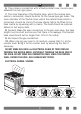
GB INTRODUCTION OF THE APPLIANCE 9 1 10 2 11 3 4 5 6 12 13 14 15 16 17 18 7* 8* 1. 2. 3. 4. 5. 6. 7. 8. Middle Burner Middle Burner Trivet WOK Burner Large Burner Auxiliary Burner Hot Plate WOK Burner 19 20 21 22 23 24 9. Glass Door 10. Control Panel 11. Led Lamp 12. Oven Control Knobs 13. Digital Timer 14. Hob Control Knobs 15. Wire Grill 16. Deep Tray 7 17. 18. 19. 20. 21. 22. 23. 24.
GB IMPORTANT WARNINGS Electrical Connection and Security 1. Your oven requires 16 or 32 Ampere fuse according to the appliance’s power. If necessary, installation by a qualified electrician is recommended. 2.Your oven is adjusted in compliance with 220-240V AC/380-415V AC 50/60Hz.electric supply. If the mains are different from this specified value, contact your authorized service. 3.
GB 6. If you make a connection with a flexible metal hose, locate a seal between the main gas pipes. 7. The inner diameter of the flexible hose, which the butane hose nozzle is connected, should be 6mm for the house-type gas tubes. The inner diameter of the flexible hose, which the natural hose nozzle is connected, should be 15mm.The hose should tightly be fitted to the hose nozzle by squeezing with a clamp. The hose should be replaced before its last expiry date. 8.
GB GAS HOSE PASSAGE WAY 1. Connect the appliance to the gas piping tap in shortest possible route and in a way that ensure no gas leakage will occur. 2. In order to carry on a tightness and sealing safety check ensure that the knobs on the control panel are closed and the gas cylindir is open. 3. While performing a gas leakage check, never use any kind of lighter, match, cigarette or similar burning substance. 4. Apply soap bubble on the connection points.
GB CHAIN LASHING ILLUSTRATION Before using the appliance, in order to ensure safe use, be sure to fix the appliance to the wall using thechain and hooked screw supplied. Ensure that the hook is screwed into the wall securely. 850 mm min. 650mm min. INSTALLATION OF YOUR OVEN 20 mm 900 mm min.
GB TECHNICAL FEATURES OF YOUR OVEN SPECIFICATIONS 90x60 Outer Width 900mm Outer Depth 610mm Outer Height 925mm Lamp Power 15W Bottom Heating Element 2000W Top Heating Element 1500W Grill Heating Element **2500W / 3250W Turbo Heating Element 1250W x 2 Supply Voltage 220-240V AC/380-415V AC 50/60Hz Hotplate 145mm* 1000W Hotplate 180mm* 1500W Hotplate Rapid 145mm* 1500W Hotplate Rapid 180mm* 2000W ** only for mix product. REDUCED GAS FLOW RATE SETTING FOR HOB TAPS 1.
GB REDUCED FLAME GAS COCK ADJUSTMENT 1. Please use driver with special head for removed and install nozzle as (Figure 5). 2. Please remove nozzle (Figure 6) from burner with special nozzle driver and install new nozzle.
GB THERMOSTAT KNOB; In order to operate the oven, thermostat must be adjusted to desired temperature. Your thermostat has a feature of adjustment to 40 - 240 degree. MECHANIC TIMER KNOB*; In order to operate the oven,timerswitch should be adjusted to desired time from 0-90 minute. You can use cooking time table.
GB USING THE BURNER GROUPS 1. Closed Fully open Half open 2. Our gas ovens top and bottom burner working system is one by one. When you want use your preference burner, before you must make press the tap knob and wait nearly 5-10 second. Then you can to inflame through with automatic ignition system (optional) or match. You must wait 10-15 second after inflame to have press by tap knob and after you can make allow the knob. If you can not made this operation you must try again. 3.
GB USING HOT PLATES* LEVEL 1 LEVEL 2 LEVEL 3 LEVEL 4 LEVEL 5 LEVEL 6 Ø80mm 200W 250W 450W --- --- --- Ø145mm 250W 750W 1000W --- --- --- Ø180mm 500W 750W 1500W --- --- --- Ø145mm Rapid 500W 1000W 1500W --- --- --- Ø180mm Rapid 850W 1150W 2000W --- --- --- Ø145mm 95W 155W 250W 400W 750W 1000W Ø180mm 115W 175W 250W 600W 850W 1500W Ø145mm Rapid 135W 165W 250W 500W 750W 1500W Ø180mm Rapid 175W 220W 300W 850W 1150W 2000W 1.
GB 2.You can balance your oven by turning the screwed feet according to the surface type you are using. 3.If your oven has plastic food as in (Figure 12) you can adjust your ovens height from these feet as turned clockwise or anticlockwise. Figure 10 Figure 11 Figure 12 USING OVEN SECTION 1. When your oven is operated first time, an odor will be spread out which will be sourced from using the heating elements. In order to get rid of this, operate it for 45 minutes while it is empty.
GB COOKING TIME TABLE WARNING: Oven must be preheated for 7-10 minutes before placing the food in it. Cooking Function Cooking Temperature (°C) Cooking Rack Cooking Time (min.
GB USING THE GRILL DEFLECTOR SHEET* 1. A safety panel is designed to protect control panel and the buttons when the oven is in grill mode. (Figure 13) Figure 13 2. Please use this safety panel in order to avoid the heat to damage control panel and the buttons when the oven is grill mode. WARNING: Accessible parts may be hot when the grill in use. Young children should be kept away. 3. Place the safety panel under control panel by opening the oven front cover glass. (Figure 14) 4.
GB CATALYTIC WALLS* Catalytic walls are located on the left and the right side of cavity under the guides. Catalytic walls banish the bad smell and obtain the best performance from the cooker. Catalytic walls also absorb oil residue and clean your oven while it’s operating. Figure 16 Removing the catalytic walls In order to remove the catalytic walls; the guides must be pulled out. As soon as the guides are pulled out, the catalytic walls will be released automatically.
GB CLEANING AND MAINTENANCE OF THE OVEN’S FRONT DOOR GLASS Remove the profile by pressing the plastic latches on both left and right sides as shown in Figure 18 and pulling the profile towards yourself as shown in Figure 19 Then remove the inner-glass as shown in Figure 20 If required, middle glass can be removed in the same way. After cleaning and maintenance are done, remount the glasses and the profile in reverse order.Make sure the profile is properly seated in its place.
GB MAINTENANCE and CLEANING 1. Disconnect the plug supplying electricity for the oven from the socket. 2. While oven is operating or shortly after it starts operating, it is extremely hot. You must avoid touching from heating elements. 3. Never clean the interior part, panel, lid, trays and all other parts of the oven by the tools like hard brush, cleaning mesh or knife. Do not use abrasive, scratching agents and detergents. 4.
GB INSTALLATION OF THE OVEN DOOR Figure 27 Figure 27.1 Completely open the oven door by pulling it to yourself. Afterwards, perform the unlocking process by pulling the hinge lock upwards with the help of a screw driver as shown in Figure 27.1. Figure 28 Figure 27.2 Bring the hinge lock to the widest angle as shown in Figure 27.2. Bring both hinges connecting the oven door to the oven to the same position. Figure 28.1 Afterwards, close the oven door as to lean on the hinge lock as shown in Figure 28.1.
GB ACCESORIES Deep Tray Used for pastries, deep fried foods and stew recipes. In case of frying directly on the grill for cakes, frozen foods and meat dishes, it can be used of oil pick-up tray. Wire Grill Used for frying and/or placing the foods to be baked, fried and frozen foods on the desired rack. Telescopic Rail* With the help of telescopic rails, the trays and/or wire racks can be easily placed and removed.
GB REMOVAL OF THE LOWER AND UPPER BURNER AND INSTALLATION OF THE INJECTOR TO THE GAS OVEN Removal of the Upper Burner: With the help of a screw driver, remove the screw as shown in Figure 29. As shown in Figure 29.1, remove the injector in the bearing with a socket wrench. In order to re-place the burner, apply the removal process reversely. Figure 29 Figure 29.1 Removal of the Lower Burner: The lower burner door has been fixed with two screws.
GB 90*60 INJECTOR, GAS FLOW And POWER TABLE BURNER SPECIFICATIONS G20,20 mbar G25,25 mbar G20,25 mbar G20,13 mbar Gas Natural Gas Natural Gas Natural Injector Wok Burner Rapid Burner Semi-Rapid Burner Auxiliary Burner Grill Burner Oven Burner 1,40 Gas Flow 0,333 mm 1,28 mm 1,60 mm m³/h 0,333 m³/h 0,333 m³/h Power 3,50 kW 3,50 kW 3,50 kW Injector 1,15 mm 1,10 mm 1,45 mm m³/h 0,276 m³/h 0,276 m³/h Gas Flow 0,276 Power 2,90 kW 2,90 kW 2,90 kW Injector 0,97 m
GB 90*60 INJECTOR, GAS FLOW And POWER TABLE BURNER SPECIFICATIONS Wok Burner Rapid Burner Semi-Rapid Burner Auxiliary Burner Grill Burner Oven Burner G30,28-30 mbar G31,37 mbar G30,50 mbar G30,37 mbar LPG LPG LPG Injector 0,96 mm 0,76 mm 0,96 mm Gas Flow 254 g/h 254 g/h 254 g/h Power 3,50 kW 3,5 kW 3,5 kW Injector 0,85 mm 0,75 mm 0,85 mm Gas Flow 211 g/h 211 g/h 211 g/h Power 2,90 kW 2,90 kW 2,90 kW Injector 0,65 mm 0,60 mm 0,65 mm Gas Flow 124
GB IF YOUR OVEN DOES NOT OPERATE 1. Please check main gas valve. 2. Gas hose is can be broken or bend. 3. Please check the connection of gas hose with oven. 4. Please check noise of gas rate. 5. Please check the gas valve, suitable or unsuitable for your oven. 6. If you can not to solve the problem, to apply manufacturer-supplier services agent or similar qualified persons. 7. We are recommended per 2 year chance your ovens gas valve. 8.
FR Cher utilisateur, Notre objectif est que ce produit fabriqué dans nos installations modernes dans un excellent environnement de travail, en conformité avec le concept de qualité totale, vous donne totale satisfaction. Par conséquent, nous vous suggérons de lire attentivement le manuel de l’utilisateur avant d’utiliser le produit et de le garder en permanence à votre disposition. Note: Ce manuel de l’utilisateur est préparé pour plus d’un modèle.
FR TABLE DES MATIERES Avertissements Importants Presentation De L’appareil Avertissements Importants Connexion Électrique Schéma Passage Pour Le Tuyau De Gaz Schéma De Connexion De La Chaine Installation De Votre Four Caracteristiques Techniques De Votre Four Instructions Pour Le Changement De Gicleur Réglage De La Réduction Du Débit De Gaz Pour Les Robinets De La Cuisinière Description Du Four Et Des Panneaux De Commande Tableaux De Bord Utilisation De La Table De Cuisson Utilisation Des Plaques Chauffante
FR AVERTISSEMENTS IMPORTANTS 1. AVERTISSEMENT: Pour éviter tout risque d’électrocution, assurez-vous que le circuit électrique du produit est ouvert avant de remplacer la lampe. 2. AVERTISSEMENT: Avant de toucher les bornes de connexion, il est indispensable de couper tous les circuits d’alimentation. 3. AVERTISSEMENT: Les parties accessibles du gril peuvent devenir chaudes lorsqu’il est en marche. Ne laissez pas les enfants s’approcher de l’appareil. 4.
FR 10. Cet appareil n’est pas raccordé à un système d’évacuation des produits de combustion. Par ailleurs, ledit appareil doit être raccordé et installé selon la législation applicable. Considérez les exigences relatives à la ventilation. 11. L’utilisation d’une cuisinière à gaz libère l’humidité et les produits de combustion dans la pièce où elle est installée.
FR 15. Cet appareil doit être installé selon les règlements et seulement dans un endroit bien aéré. Lisez les instructions avant d’installer ou d’utiliser l’appareil. 16. Avant d’installer l’appareil, vérifiez les conditions locales (type de gaz et pression du gaz) et assurez-vous que les réglages de l’appareil sont appropriés. 17. Ces instructions sont applicables pour les pays dont les symboles sont indiqués sur l’appareil.
FR 23. Après avoir introduit un plat, assurez-vous que le porte est bien fermée. 24. Ne laissez pas les enfants de moins de 8 ans sans supervision s’approcher de l’appareil. 25. Évitez de toucher les éléments chauffants, au risque de vous brûler. 26.
FR PRESENTATION DE L’APPAREIL 9 1 10 2 11 3 4 5 6 12 13 14 15 16 17 18 7* 19 20 21 22 23 8* 1. 2. 3. 4. 5. 6. 7. 8. Brûleur Central Brûleur Central Grille WOK Brûleur Grand Brûleur Auxiliaire Brûleur Plaque Chauffante WOK Brûleur 24 9. Porte en Verre 10. Panneau de Commande 11. Lampe Led 12. Boutons de commande du four 13. Minuteur Digital 14. Boutons Plaques de Cuisson 15. Grille 16. Plaque Profonde 35 17. Porte du Four 18. Poignée du Four 19. Porte de l’armoire du bas 20.
FR AVERTISSEMENTS IMPORTANTS Connections Electrique Et Sécurité 1.Votre four est réglé en conformité avec une alimentation électrique de 220-240V / 380-415V AC, 50/60 Hz. Si le courant est différent de cette valeur spécifiée, contactez votre centre de service autorisé. 2.L’installation électrique du four doit être uniquement effectuée par le réseau avec liaison de terre, installé selon les lois en vigueur.
FR 6.Le diamètre interne du tuyau flexible, avec lequel le tuyau du butane est relié, doit être de 6mm pour les tuyaux à gaz de maison. Le diamètre interne du tuyau flexible, avec lequel le robinet du flexible est relié, doit être de 15 mm. Le tuyau doit être fermement fixé avec le robinet du flexible en serrant avec une pince. Le tuyau doit être remplacé avant sa date d’expiration. 7.
FR PASSAGE POUR LE TUYAU DE GAZ 1. Branchez l’appareil sur le robinet de la tuyauterie de gaz suivant l’itinéraire le plus court possible et de telle sorte qu’aucune fuite de gaz ne puisse être enregistrée. 2. Pour effectuer le contrôle d’étanchéité, assurez-vous que les poignées du panneau de commande sont fermées et que la bouteille de gaz est ouverte. 3. Lors d’une vérification de fuite de gaz, évitez d’utiliser tout type de briquet, allumette, cigarette ou substance similaire. 4.
FR SCHÉMA DE CONNEXION DE LA CHAINE Pour être sûr d’utiliser le produit en toute sécurité, assurez-vous que le produit est fixé sur le mur avec une chaine et un vis crochet avant d’utiliser l’appareil. Assurez-vous que le crochet est vissé de façon sécurisée sur le mur. 850 mm min. 650mm min. INSTALLATION DE VOTRE FOUR 20 mm 900 mm min.
FR CARACTERISTIQUES TECHNIQUES DE VOTRE FOUR CARACTÉRISTIQUES 90x60 Largeur Extérieure 900mm Profondeur Extérieure 610mm Hauteur Extérieure 925mm Puissance Ampoule 15W Elément Chauffant Du Bas 2000W Elément Chauffant Du Haut 1500W Elément Chauffant Du Grill **2500W / 3250W Elément Chauffant Turbo 1250W x 2 Tension D’alimentation 220-240V AC/380-415V AC 50/60Hz.
FR 3. Utilisez un tournevis de taille appropriée pour régler la vis de réglage du débit. Pour le GPL (Butane - Propane), tournez la vis dans le sens horaire. Pour le gaz naturel, tournez la vis une fois dans le sens antihoraire. « La longueur normale d’une flamme droite en position réduite doit être de 6 à 7 mm. 4. Si la flamme est plus élevée que la position souhaitée, tournez la vis dans le sens horaire. Dans le cas contraire, tournez-la dans le sens antihoraire. 5.
FR DESCRIPTION DU FOUR et des PANNEAUX DE COMMANDE Tourne Broche (Grıll Poulet) Seulement Ventilateur Se Fonctionne Chauffant Supérieure Et Inferieure & Se Fonctionnent Instrument Chauffant Turbo + Ventilateur Lampe Chauffant Supérieure Et Inferieure & Sefonctionnent + Seulement Ventilateur Instrument Chauffant Inferieure + Seulement Ventilateur Se Fonctionne Grille Chauffant Et Ventilateur Se Fonctionnent Grill Heating Element + Tournebroche Grille Chauffant Se Fonctionnent Grille Chauffant Se Fo
FR UTILISATION DE LA TABLE DE CUISSON 1. Ferme Entièrement ouvert A moitié ouvert 2. Afin d’assurer une utilisation optimale, assurez vous que la casserole utilisée ait un fond plat, et utilisez des casseroles aux dimensions indiquées ci-dessous Le robinet de contrôle de la cuisinière à gaz ont un mécanisme spécial. Afin d’allumer la cuisinière; 3.
FR UTILISATION DES PLAQUES CHAUFFANTES* NIVEAU 1 NIVEAU 2 NIVEAU 3 NIVEAU 4 NIVEAU 5 NIVEAU 6 Ø80mm 200W 250W 450W --- --- --- Ø145mm 250W 750W 1000W --- --- --- Ø180mm 500W 750W 1500W --- --- --- Ø145mm Rapide 500W 1000W 1500W --- --- --- Ø180mm Rapide 850W 1150W 2000W --- --- --- Ø145mm 95W 155W 250W 400W 750W 1000W Ø180mm 115W 175W 250W 600W 850W 1500W Ø145mm Rapide 135W 165W 250W 500W 750W 1500W Ø180mm Rapide 175W 220W 300W 850W 1150W 2000
FR 3. Vous pouvez stabiliser votre four en serrant ou desserrant les vis selon le type de surface. Dessin 10 Dessin 11 Dessin12 UITILISATION DU FOUR 1.Les brûleurs à gaz du four en haut et en bas fonctionnent indépendamment l’un de l’autre. Lorsque vous voulez utiliser votre brûleur préféré, il vous faut d’abord appuyer sur le bouton et attendre environ 5-10 secondes. Vous pouvez alors allumer les brûleurs avec le système d’allumage automatique (en option) ou une allumette.
FR 6.Temps de cuisson: les résultats peuvent varier selon: le voltage, local la qualité, la quantité ou la température du matériel Pendant le temps de cuisson au four, la vitre du four doit être ouverte fréquemment. 7.Sinon, la circulation de la chaleur peut être perturbée et les résultats peuvent alors changer; Utiliser des moules à gâteau lors de la cuisson permette l’obtention d’un meilleur résultat. AVERTISSEMENT: Le four doit être préchauffé pendant 7 à 10 minutes avant d’y placer des aliments.
FR UTILISATION DE L’ECRAN DE PROTECTION* 1. Un panneau de sécurité a été conçu pour la protection du panneau de commande et ses boutons lorsque le four est en mode gril. (Dessin 13) Dessin 13 2. Placez le panneau de sécurité sous le panneau de commande en prenant le soin d’ouvrir la vitre du couvercle avant du four (Dessin 14) 3. Ensuite, fixez le panneau de sécurité entre le four et le couvercle avant en fermant doucement ce dernier. (Dessin 15) Dessin 14 4.
FR PAROIS CATALYTIQUES* Les parois catalytiques se trouvent à gauche et à droite de la cavité située sous les guides. Les parois catalytiques expulsent la mauvaise odeur et permettent d’obtenir une meilleure performance de la cuisinière. Elles absorbent également les résidus d’huile et nettoient votre four lorsqu’il est en marche. Dessin 16 Retrait des parois catalytiques Pour retirer les parois catalytiques, vous devez retirer les guides.
FR NETTOYAGE ET ENTRETIEN DE LA VITRE DE LA PORTE AVANT DU FOUR Retirez le profilé en appuyant sur les loquets en plastique des côtés gauche et droit, comme illustré à la Dessin 18, et tirez-le vers vous, comme illustré à la Dessin 19. Puis, retirez la vitre intérieure, comme illustré à la Dessin 20. Au besoin, procédez de la même manière pour le retrait de la vitre du milieu. Une fois le nettoyage et l’entretien achevés, replacez les vitres et le profilé dans l’ordre inverse.
FR MAINTENANCE et NETTOYAGE 1. Déconnectez la prise male, alimentant le four en électricité, de la prise murale. 2. Pendant que le four marche ou peu après, il est extrêmement chaud. Il vous faut éviter de toucher les éléments chauffants. 3. Ne nettoyez jamais la partie intérieure, le panneau, le couvercle, les tiroirs et toutes les autres pièces du four avec des outils comme une brosse dure, une éponge métallique ou un couteau. N’utilisez pas de produits abrasifs, qui rayent et des détergents. 4.
FR ASSEMBLAGE DE LA PORTE DU FOUR Dessin 27 Dessin 28 Dessin 27.1 Dessin 27.2 Dessin 28.1 Dessin 28.2 Ouvrir complètement la porte du four en la tirant vers vous. Puis, comme indiqué sur le Dessin 27.1, réalisé l’opération de déverrouillage en tirant vers le haut le verrou de la charnière à l’aide d’un tournevis. Positionnez le verrou de la charnière au degré d’angle le plus grand comme sur le Dessin 27.2. Positionner de la même façon les deux charnières qui attachent la porte du four au four.
FR LES ACCESSOIRES Plaque Profonde Utilisée pour les farinages, grandes fritures et plats avec sauces.Pour les cakes, plats congelés et plats avec viande, il peut aussi être utilisé comme récupérateur de gras en cas de grillade sur la grille. Grille Utilisée pour les plats à rôtir, frire ou pour installer les produits congelés sur l'étagère souhaitée. Rails Télescopique* Grâce aux rails télescopiques, les plaques et étagères peuvent être facilement retirées et insérées.
FR DESASSEMBLAGE DES BRULEURS DU HAUT ET DU BAS DU FOUR A GAZ ET FIXATION DES INJECTEURS Désassembler le brûleur du haut: With the help of a screw driver, remove the screw as shown in Dessin 29. As shown in Dessin 29.1, remove the injector in the bearing with a socket wrench. In order to re-place the burner, apply the removal process reversely. Dessin 29 Dessin 29.1 Désassembler le brûleur du bas: The lower burner door has been fixed with two screws.
FR 90*60 INJECTEUR, CONSUPTION et PUISSANCE TABLEAU VALEURS DES INJECTEURS DE BRULEUR SELON LE TYPE DE GAZ G20,20 mbar G25,25 mbar G20,25 mbar G20,13 mbar Gaz Naturel Gaz Naturel Gaz Naturel Injecteur Wok Brûleur Grand Brûleur Brûleur Moyen Petit Brûleur Brûleur du Haut Grill Brûleur du Bas Four 1,40 Consuption 0,333 mm 1,28 mm 1,60 mm m³/h 0,333 m³/h 0,333 m³/h Puissance 3,50 kW 3,50 kW 3,50 kW Injecteur 1,15 mm 1,10 mm 1,45 mm m³/h 0,276 m³/h 0,276 m³/h Consupti
FR 90*60 INJECTEUR, CONSUPTION et PUISSANCE TABLEAU VALEURS DES INJECTEURS DE BRULEUR SELON LE TYPE DE GAZ Wok Brûleur Grand Brûleur Brûleur Moyen Petit Brûleur Brûleur du Haut Grill Brûleur du Bas Four G30,28-30 mbar G31,37 mbar G30,50 mbar G30,37 mbar LPG LPG LPG Injecteur 0,96 mm 0,76 mm 0,96 mm Consuption 254 g/h 254 g/h 254 g/h Puissance 3,50 kW 3,5 kW 3,5 kW Injecteur 0,85 mm 0,75 mm 0,85 mm Consuption 211 g/h 211 g/h 211 g/h Puissance 2,90 kW 2,90 k
FR SI VOTRE FOUR NE FONCTIONNE PAS 1.Merci de vérifier la valve principale du gaz 2.Le tuyau à gaz peut être cassé ou noué. 3.Merci de vérifier le branchement du tuyau à gaz avec votre four. 4.Merci de vérifier le bruit du niveau du gaz 5.Merci de vérifier le tuyau du gaz, compatible ou non avec votre four. 6.Si vous ne parvenez pas à résoudre le problème contacter le fournisseur-constructeur ou une personne compétente. 7.Nous vous recommandons de changer la valve à gaz tout les deux ans. 8.
SA إذا الفرن الخاص بك ال تعمل .1الرجاء مراجعة صمام الغاز .2ممكن ان يكون خرطوم الغاز مكسور او مطعوج .3الرجاء التحق بين اتصال الفرن و الغاز .4الرجاء التحق من معدل صوت الغاز .5الرجاء التحق من صمام الغاز هل هو مناسب لي فرنك ام ال .6اذا لن تنحل المشكله راجع مندوب او وكيل المصنع .7نحن نوصيكم بتغيير الصمام في العام مرة او مرتين .8يرجى التحقق من من السلك او مصدر الطاقه لديها مأخذ جيدا ام ال .9يرجى التحقق من وصول الكهرباء .10يرجى التحقق من صمامات الكهرباء .
SA 06x09 محقنة ,استهالك و طاقة جدول G20,13 mbar G20,25 mbar G20,20 mbar G25,25 mbar غاز طبيعي غاز طبيعي غاز طبيعي عقارات mm 06,1 mm 82,1 mm 04,1 محقنة m³/h 333,0 m³/h 333,0 m³/h 333,0 استهالك kW 05,3 kW 05,3 kW 05,3 طاقة mm 54,1 mm 01,1 mm 51,1 محقنة m³/h 672,0 m³/h 672,0 m³/h 672,0 استهالك kW 09
SA 06x09 محقنة ,استهالك و طاقة جدول G30,37 mbar G30,50 mbar G30,28-30 mbar G31,37 mbar LPG LPG LPG mm 69,0 mm 67,0 mm 69,0 محقنة g/h 452 g/h 452 g/h 452 استهالك kW 5,3 kW 5,3 kW 05,3 طاقة mm 58,0 mm 57,0 mm 58,0 محقنة g/h 112 g/h 112 g/h 112 استهالك kW 09,2 kW 09,2 kW 09,2
SA فك الحوارق العلوية والسفلية للفرن الغازي وتركيب الفوهات فك الحوارق العلوية: وموا بفك البرغي باستخدام مفك البراغي وكما هو موضح بالشكل 72قوموا بإخراج الفوهة من مكانها بإستخدام مفاتيح اللقمة وكما هو موضح بالشكل 27,1إلعادة وضع الحوارق في مكانها قوموا بالتطبيق العكسي إلجراءات الفك.
SA االكسسوارات الصينية العميقة تستخدم للمعجنات وللقلي الكبير والمأكوالت ذات المرقة. يمكن استخدامها للكيك واالطعمة المجمدة ولطبخات اللحم كوعاء لتجميع الزيت في حالة الشوي على الشواية مباشرة . شواية الشبك تستخدم للشوي أو لوضع األطعمة المجمدة أو التي سيتم شويها او طبخها بالفرن على الرف المطلوب. *السكة التلسكوبية بفضل السكك التلسكوبية يمكن فك وتركيب الصواني أو رف الشبك.
SA تركيب باب الفرن صورة 28 صورة 28,2 صورة 27 صورة 28,1 إلخراج باب الفرن، بعد ذلك قوموا بغلق قوموا بسحب باب باب الفرن الذي قمتم الفرن الى االعلى وكما بفتحه وكما هو موضح هو موضح بالشكل بالشكل صورة 28,1 صورة 28,2بمسكه ولحين وصوله الى باليدين عندما يصل موقعأرتكائه بقفل الى مستوى مقارب المفصل. للوضع المغلق. صورة 27.3 صورة 27,1 قوموا بفتح قفل المفصل وكما هو موضع بالشكل صورة 27.3وجعله بأوسع زاوية .
SA الصیانة والتنظیف .1اسحبوا المأخذ عن الكھرباء و اقطعوا خط الغاز باغالق صمامة الغاز. .2ان الجھاز ساخن اثناء التشغیل او ما بعد التشغیل بوقت یسیر .احذروا مالمسة عناصر التسخین فى مثل ھذه االوقات . .3ال تقوموا بتاتا بتنظیف االجزاء الداخلیة للجھاز و اللوحة و الغطاء و الصینیة و القطع االخرى باستعمال الفرشاة الصلبة او منظف االوانى الحدیدى او اآلالت الحادة مثل السكین. .4و ال تستعملوا المواد و مساحیق الغسیل المركزة . .
SA صيانة وتنظيف زجاج الباب األمامي في الفرن اضغط على المغالق البالستيكي الموجود على الطرف األيمن واأليسر كما ھو مبين في الشكل 16 واسحبهما نحوك كما ھو مبين في الشكل 17وانزع القضيب المعدني .ثم أخرج اللوح الزجاجي من مكانھ كما ھو مبين في الشكل . 18يمكن إخراج الزجاج الداخلي أيضا بنفس الطريقة عند الطلب .بعد االنتهاء من الصيانة والتنظيف قم بإعادة اللوح الزجاجي والقضيب إلى مكانھ بترتيب معاكس .
SA الجدران الحفازة تقع الجدران الحفازة على اليسار وعلى الجانب األيمن من تجويف تحت الدعامات .تمنع الجدران الحفازة الرائحة الكريهة و تساعد على الحصول على أفضل أداء في الطبخ. كما تمتص الجدران الحفازة بقايا النفط وتنظف الفرن في حين و هو في وضع التشغيل صورة 16 إزالة الجدران الحفازة إلزالة الجدران الحفازة ،يجب سحب الدعامات .في حال سحب الدعامات ،سيتم إزالة الجدران الحفازة تلقائيا .يجب إستبدال الجدران الحفازة كل 2-3سنة شواء الدجاج ضع السيخ على اإلطار .
SA جدول الطهي تحذير :يجب تسخين الفرن لمدة 7-10دقائق قبل وضعه الطعام في ذلك.
SA تجهيز السيقان لغرض تركيبها: .1توضح الصورة ( )10وجود قضيب خاص أسفل الفرن لتركيب السيقان المتحركة .حيث هناك صوامل خاصة لشد السيقان الصورة( .)10ويتم شد الصوامل إلحكام السيقان كما هو موضح في الصورة()11 .2يمكن تحقيق توازن الفرن عبر تغيير مستوى السيقان المتحركة بواسطة اللوالب المخصصة لهذا الغرض صورة 10 صورة 12 صورة 11 استخدام قطاع البوتجاز .
SA .6و اعیدوا نفس العملیة فى حالة عدم استطاعتكم لالشعال . .
SA كيفية إستخدام الفرن .1عند إستخدامكم الفرن ألول مرة ستنبعث مميزة منه ومصدرها عناصر التسخين الموجودة فيه وألجل التخلص من هذه الرائحة ينبغي تسخين الفرن ولمدة 45دقيقة. .2عند إستعمالكم للفرن الذي رجحتموه يجب أوالً الضغط على زر الصنبور(لفتح الغاز) حتى يصل إلى الوضع ولمدة 10–5ثانية. .3وبعدها يمكنكم تشغيل الفرن بواسطة زر اإلشعال ،ولكن يجب إستمرار الضغط على الزر لمدة 10-5 ثانية بعد حدوث اإلشتعال ومن ثم يترك. .4وإذا فشلتم في إشعال الفرن أعد المحاولة مجدداً. .
SA تعریف بالفرن و لوحات المراقبة مروحة محرك و شوایة دجا ج شعلة كھ ربائیة دائریة مع مروحة شعلة علویة و سفلیة شعلة علویة و سفلیة مع مروحة مصباح شوایة كھربائیة مع مروحة شعلة سفلیة و مروحة شوایة كھربائیة /شعلة علویة شوایة كھربائیة مع محرك و شوایة دجاج شعلة علویة شوایة كھربائیة مع مصباح شعلة سفلیة ساعة میكانیكیة اشعال ذاتي شعلة شواية صغير شواية صغيرة و مروحة لوحة التحكم مالحظة :فيما يلي معنى الرموز الموجودة على لوحة تحكم الجهاز .
SA عملية تغيير الحلمة :يرجى استخدام مف ّ ك ذي رأس خاص الزالة الحلمة وتركيبها كما في صورة. ك خاص بها وتركيب حلمة جديدة (صورة )7 يرجى نزع الحلمة (صورة )6من الموقد بمف ّ صورة 6 صورة 7 صورة 5 إعداد معدل التدفق المنخفض لمحابس الموقد .1قم بإشعال الشعلة التي ترغب في ضبطها وقم بلف مقبض التحكم إلى وضع التدفق المنخفض .2أخرج المقبض من محبس الغاز .
SA مواصفات 90x60 العرض 765 ملم العمق 410 ملم اإلرتفاع 355 ملم قدرة المصباح 15 وات عنصر التسخين الـ ـتربو 2000 وات عنصر التسخين العلوي 1500 وات مشبك التسخين 3250 / **0052 وات مشبك التسخين 1250x2 وات 60/ 50هيرتز 240-220 /فولت 415/380 /فولت، الفولتية الداخلة اللوحة الساخنة(الفرن الكهربائي) 145أوم* 1000 وات اللوحة الساخنة(الفرن الكهربائي) 180أوم* 1500 وات اللوحة الساخن
SA ةلسلس طبر خرطوم مرور الغاز .1قم بتوصيل الجهاز مع صنبور أنابيب الغاز في أقصر طريق ممكن وبطريقة تضمن أن ال .يحدث أي تسرب للغاز .2من أجل االستمرار في إحكام وختم فحص السالمة ،تأكد من أن المقابض على لوحة التحكم ال .تعمل واسطوانة الغاز مفتوحة .3أثناء إجراء فحص تسرب الغاز ،ال تستخدم أي نوع من الوالعات ،عود الثقاب ،السجائر أو .مادة حرق مماثلة .4ضع فقاقيع الصابون على نقاط الوصل .إذا كان هناك أي نوع من التسرب ،فسوف تظهر .الفقاقيع على السطح .
SA .6يجب أن يكون القطر الداخلي لرأس الخرطوم الذي يربط بخرطوم غاز البيوتان للقناني المنزلية 6ملم أم ذلك للغاز الطبيعي فيجب أن يكون 15ملم .ويجب أن يربط الخرطوم بالرأس المخصص له بواسطة حلقة إحكام مع شدها .7بإحكام .ويجب تغيير الخرطوم قبل إنتهاء صالحيته .8إنتباه! يجب ربط الغاز بصنبور المخصص لذلك .ويجب أن يكون الخرطوم قصيراً مع الـتاكد من عدم وجود أي تسرب .ومن األفضل أن ال يتجاوز طول الخرطوم 125سم. .9تأكد من سالمة ربط الغاز .
SA كيفية تجهيز الفرن الربط الكهربائي وشروط األمان .1يعمل الجهاز وفق جهد كهربائي متناوب ذي 240-220فولت وترددv/380-415 v240-240 ترباز و 16او 32امبير كهربه هرتز .وإذا كان الجهد الكهربائي الموصول للمنزل مختلفا ً عن هذه المقلييس ينبغي عندئذ اإلتصال بوكيل معتمد للخدمة الفنية. ً .2يجب األخذ بنظر اإلعتبار كون التأسيسات الكهربائية ذات قوابس موصلة أرضيا عند مدها وحسب الطرق الفنية المعتمدة .
SA التعريف بالجهاز 9 2 10 1 11 6 4 5 12 13 14 15 16 3 17 18 19 20 *7 21 22 23 *8 24 .10لوحة التحكم .1الموقد (بيك) المتوسط .11مصباح قسم الفرن .2الموقد (بيك) المتوسط .12إعداد الثيرموستات .3المنصب .13المؤقت الرقمي .4الطباخ العريض .14موقد مقبض التحكم .5الموقد (كبير) المتوسط .15الشواية .6الموقد (صغير) المتوسط .16الصينية العميقة .
SA .14توجد تجهيزات واقية إضافية لمنع مالمسة أبواب الفرن دون قصد .يجب تركيب هذه التجهيزات في حالة وجود أطفال .15يجب تركيب هذا الجهاز وف ًقا لضوابط التركيب وفي مكان جيد التهوية فقط“. ”.اقرأ التعليمات قبل تثبيت الجهاز أو تشغيله .16قبل وضع الجهاز ،راجع الظروف المحلية (نوع الغاز وضغط الغاز) وتأكد“ ”.من أن إعدادات الجهاز مالئمة لها .17تسري هذه التعليمات على الدول التي تم ذكر رموزها على الجهاز .
SA تحذيرات مهمة .1تحذير :لتجنب التكهرب ،تأكد من فتح الدائرة الكهربائية للمنتج قبل استبدال اللمب .2تحذير :قبل مالمسة أطراف التوصيل ،يجب فصل جميع دوائر اإلمداد .3تحذير :أثناء تشغيل الشواية ،قد تكون األسطح التي يمكن الوصول إليها ساخنة .ابق األطفال بعيدًا .4تحذير :الطهي بدون مراقبة باستخدام زيوت أو دهون يمكن أن يمثل خطورة ويتسبب في نشوب حريق .
SA عربى فرن الغاز دلیل االستعمال عزیزى المستعمل! ان غایتنا ھى تحقیق ھذا المنتج الذى تم تصنیعه بمصانعنا المتطورة فى بیئة عمل مالئمة لنظام الجودة المجموعة و بدقة عالیة أحسن النتائج لكم دائما. و تحقیقا لھذه الغایة نوصیكم بمطالعة دلیل االستعمال قبل البدء بتشغیله و االحتفاظ به دوما حتى یتیسر لكم الرجوع الیه حین الحاجة.
فرن قا ئمة بذاتها الغاز ومع الكهربائية 90x60 USER MANUAL GB MANUEL D’INSTRUCTIONS FR SAدليل المستخدم