i CONTENTS 1 INTRODUCTION 1 Instrument overview .............................................................................................................. 2 Instrument specifications ....................................................................................................... 3 Safety warnings .................................................................................................................... 3 2 UNPACKING AND ASSEMBLY 5 Unpacking the CMRV-5000 .........................
ii 6 PREPARING FOR CMRV TESTING/CALIBRATION 27 Cleaning cycle .................................................................................................................... 27 Cleaning procedure ................................................................................................. 27 Inserting rotors ....................................................................................................... 30 7 CALIBRATING THE CMRV TEMPERATURE PROBE 31 Probe calibration procedure ......
iii 10 SUMMARY OF TEST PROCEDURE 55 ASTM D 4684 method ...................................................................................................... 55 ASTM D 3829 method ...................................................................................................... 56 ASTM D 6821 method ...................................................................................................... 56 ASTM D 6896 method ..............................................................................
iv 14 DESIGNING CUSTOMIZED PROFILES 79 Cooling Profiles .................................................................................................................. 79 The Profile Designer ........................................................................................................... 79 Opening the Profile Designer ................................................................................... 80 Interface options ....................................................................
v A APPENDIX A — TROUBLESHOOTING 107 Instrument status window not updating .................................................................. 107 The CMRV is not heating properly ........................................................................ 107 The Yield/Viscosity lights on the CMRV Controller front panel are blinking rapidly. . 107 CMRV cooling/temperature control problems ........................................................ 107 Yield stress or viscosity test results inconsistent. ......
vi This page intentionally left blank. CANNON ® Mini-Rotary Viscometer CMRV-5000 Instruction & Operation Manual Version 1.
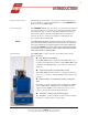
1 CHAPTER INTRODUCTION 1 Purpose of the manual This manual has been written to provide the information necessary for proper installation, operation, and maintenance of the CANNON ® MiniRotary Viscometer (CMRV-5000). Instrument utility The CANNON ® Mini-Rotary Viscometer is used to measure the apparent viscosity and yield stress of engine oils and drive line lubricants within the temperature range of -10°C to -40°C using ASTM test methods D 4684, D 3829, D6821 and D 6896.
2 Networking capability for multiple instruments The VISCPRO® software can control/monitor up to four CMRV instruments with one computer via RS-485 serial connections. See APPENDIX D for more information. Instrument overview The CANNON ® Mini-Rotary Viscometer is designed for precision control of temperature over time, enabling accurate yield stress and viscosity measurement of oil samples in conformance with ASTM D 3829, ASTM D 4684, ASTM D 6821 and ASTM D 6896 test methods.
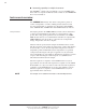
3 Instrument specifications CMRV-5000 SERIES SPECIFICATIONS Dimensions 284 mm wide × 396 mm deep × 617 mm high* (11.2 × 15.6 × 24.3") Weight 23 kg (50 lbs) Shipping Weight 32 kg (70 lbs) Operational temperature 80°C to -40°C Operating Conditions 15°C-30°C, 10%-90% RH non-condensing; Installation category II Pollution degree 2 Fuse Rating M 5A 250V; 1¼" × ¼" Compliance EMC directive (89/336/EEC); Low voltage directive (73/23/EEC) HI-POT (1900 VDC, 60 sec.
4 General Caution Hot Surface Caution In addition to the warnings previously listed, additional cautions are posted throughout the manual. These warnings may be designated by an appropriate symbol inside an equilateral triangle. General cautions are indicated with an exclamation point (see diagram, left). Read and follow these important instructions. Failure to observe these instructions can result in permanent damage to the unit, significant property damage, and personal injury.
5 CHAPTER UNPACKING AND ASSEMBLY 2 Unpacking the CMRV-5000 CAUTION Some CMRV components are quite heavy. To avoid injury, obtain necessary assistance when lifting and moving shipping cartons and heavier unpacked components. Remove all components from the shipping container(s). Remove shipping screws from both fans. Remove any and all packing materials (styrofoam, etc.) from the components. Verify reception of shipped materials by comparing equipment items with packing/parts list(s).
6 Set of weights: One 150-gram weight • One hook-cage • Nine additional weights 1 Bottle of N105B with test sample and data sheet 1 Tube thermal paste (for mounting temperature probe) Plexiglas® Top Cover Instruction & Operation Manual 5 rotor bearing pins 5 rotor locking pins Cell holder Optional rotor stand and drain pan set User-Supplied Equipment The user must supply an electrical power source matching the electrical requirements indicated on the rear panel of the CMRV-5000 Controlle
7 CHAPTER CMRV-5000 APPARATUS DESCRIPTION 3 CMRV-5000 unit/accessories The CMRV-5000 unit is comprised of a head unit and Controller. The head unit contains an aluminum block with a heater for warming and thermoelectric modules for cooling. Five viscometric cells are closely fitted into the holes in the block (see photo). There are also two thermometer wells in the block. The Controller contains the microprocessor, power supply and related electronics.
8 Upper rotor bearing The upper bearing consists of a brass insert at the top of the rotor shaft with a 1.2 mm hole on the shaft axis. A cylindrical rotor pin is inserted through the upper bearing plate about one or two millimeters into the hole on the shaft axis. Rotor crossbar The rotor crossbar is used to hold the loop at the end of the thread. It also serves as an indicator for (optional) manual timing of rotor rotation, and engages the rotor locking pin through the cooling cycle.
9 weight are provided. Weights vary depending on the ASTM Method used for testing. Temperature probe CMRV-5000 block temperature is detected by a 3k-ohm temperature probe, which must be seated securely in the thermistor aperture at the side of the CMRV housing and plugged into the electronic chassis. Thermometers The CMRV-5000 unit is shipped from CANNON® with two thermometers to be used to check the temperature of the block.
10 diodes (LEDs) indicate function of the heating and cooling systems. The Lemo jack connection (labeled WHEEL) on the front of the panel mates with the cable from the pulleywheel optical sensor (Do NOT plug or unplug the pulleywheel assembly when the instrument power is ON). The Start Test button is used to initiate CMRV-controlled testing and calibration routines. The Yield and Viscosity LEDs light during yield stress or viscosity testing.
11 CHAPTER SETUP 4 The instructions in this chapter are for setting up a single CMRV-5000. For additional information on multi-unit configurations, see APPENDIX D. Physical placement CAUTION The CMRV instrument is quite heavy. To avoid injury, obtain necessary assistance when lifting and moving instrument components. Placement Place the CMRV-5000 Controller/base unit on a stable laboratory bench within 10 mm of the front edge.
12 CMRV Head Unit rear panel Installing thermistor CMRV Controller rear panel CMRV-5000 power cord CAUTION Make sure the CMRV-5000 power switch is in the OFF position. Then insert the power line cord from the rear panel of the CMRV Controller into an appropriate power source for your unit Before providing mains power to the unit, check the label on the rear panel of the Controller/Controller to verify that the electrical specifications for the unit match the mains.
13 Serial connections NOTES To connect a single CMRV-5000 instrument to the host computer, connect the computer cable to the RS-232, DB-9-pin socket at the rear of the CMRV-5000 Controller and secure the cable connection with the two small screws on the ears of the plug. Attach the other end of the cable to the RS-232 port at the rear of your computer. COM 2 and COM 4 use the same IRQ settings on most computers, meaning that they cannot be used simultaneously.
14 CAUTION Do NOT plug or unplug the pulleywheel assembly when the instrument power is ON! To disconnect the sensor, pull it out by the knurled portion of the plug. Firmware installation notes Download button Current firmware is installed on your instrument during factory checkout. However, the CMRV-5000 is capable of receiving firmware updates from the computer.
15 3. Attach the quick connect tubing from the matching connector on the regulator to the PURGE IN connector on the head unit rear panel. Secure both connections by turning the tube fitting clockwise until the connection snaps securely into place. If necessary, turning the tube fitting counterclockwise will release the connection. 4. Attach the regulated pressure line from your nitrogen source (3 psig maximum recommended) to the fitting opposite the flow adjust control on the gas purge regulator. 5.
16 This page intentionally left blank. CANNON® Mini-Rotary Viscometer CMRV-5000 Instruction & Operation Manual Version 1.
17 CHAPTER VISCPRO® INSTALLATION 5 VISCPRO ® for Windows ® XP® VISCPRO® is a powerful software product providing a generic instrument interface for controlling and operating multiple CANNON® instrument(s) via computer. VISCPRO® also includes reporting/analysis modules for processing and displaying sample data. Installing VISCPRO ® software To install the VISCPRO® software, follow the instructions below in the sequence presented.
18 Running the software Loading software Make certain that your CMRV instrument is properly connected to your computer and the CMRV power switch is ON. Then start the VISCPRO® software by double-clicking the VISCPRO® icon on your Windows® desktop. Or click Start/Programs/VISCPRO/VISCPRO.EXE).
19 The Instrument View window NOTE To display the Instrument View window, click View Instrument from the Main menu. The View Instrument window will appear. Then click the MRV instrument ID to display the list of available configurations. For now, select the default configuration and click OK. Instrument ID/Type Instrument Configuration If the Available Instruments list box is blank, your instrument(s) may not be on-line. Check cable connections and make certain the instrument power switch is ON.
20 Viewing report data After you have completed CMRV calibration and testing (see next chapters), you will be able to display a report window with CMRV-5000 test results. To access the database and display test data, click Analyses/ View Analysis.
21 Checking Configuration data Follow the procedures in the next several sections of this chapter to select and verify the instrument and calibration settings to ensure that they conform to the actual characteristics of your CANNON® instrument. Verifying configuration To check the configuration settings for your instrument(s), you must log in to the security system as a manager. The software is installed with a default Manager account.
22 The Instrument Settings window 4. Use the ID field to input instrument identification information using up to 30 alphanumeric characters. The remaining fields in the Instrument Settings window are noneditable (information is obtained via serial communication with the CMRV instrument). The Model: field will indicate the model of your instrument. The S/N: field indicates the serial number from the label on the Controller rear panel.
23 The View Cell Constants window 3. Click Configuration/Print Instrument Settings to open the Windows® Print window. Select the desired printer and click OK to print current calibration settings. NOTE CANNON recommends printing calibration settings each time the calibration values change. Setting multiple CMRV instrument addresses When installing/connecting multiple CMRV instruments, ensure that the instrument address for each instrument is different.
24 Initial security setup The VISCPRO® software installation creates a security account for one manager with a blank password. After VISCPRO® installation, a password should be assigned for the manager using the Change Password menu option from Main. Managers may add or change accounts for technician status personnel. Use the Log In feature to identify the CMRV operator and/or access security functions.
25 4. Click Update User Information from Main. 5. Select the desired user from the User Name list box. NOTE To delete a user, just click Remove User after selecting the user name. The account will be immediately and permanently removed. 6. Enter and verify the desired password, and select user security status using the appropriate list boxes. 7. Retype the password in the Confirm Password field. 8. Click Add or Update User to save your changes. 9. Click Done to exit the Change User List window.
26 This page intentionally left blank. CANNON® Mini-Rotary Viscometer CMRV-5000 Instruction & Operation Manual Version 1.
27 CHAPTER PREPARING FOR CMRV TESTING/CALIBRATION 6 The procedures in this chapter should be followed when preparing for CMRV-5000 testing or calibration. NOTE In the event that the protocols of your ASTM test method differ from any of the procedures outlined in this manual, the ASTM method should take precedence. Providing power To prepare for operation of the CMRV-5000 unit, turn on the POWER switch on the front panel of the Controller.
28 CAUTION! Exposure to acetone liquid or acetone vapor may damage the cover. 2. Ensure that the CMRV instrument power switch is on. NOTE The CMRV cleaning procedure may be initiated from a "cold" CMRV; however, a calibration or profile should not be initiated until the instrument has completed a warmup period of approximately 45 minutes. If the warm-up period is less than 45 minutes, the instrument may not control temperature within acceptable tolerance parameters. 3.
29 NOTE When the CMRV-5000 cleaning cycle is activated, the internal heater raises the viscometer block temperature 2-3°C per minute to approximately 50°C. Precise temperature control is not necessary for cleaning. 9. When the CMRV-5000 has reached cleaning temperature remove the rotors and wipe excess oil from them. Gently place the rotors into a solvent-resistant container, such as a 500-ml glass beaker. CAUTION Be careful not to damage the rotor tips when handling the rotors. 10.
30 Inserting rotors The viscometric cells are individually marked, and are calibrated with their rotors as a matched set. For consistency, it is recommended that cell/rotor #1 be placed in the left-most position in the block, cell/rotor #2 be placed in the adjacent position, and so forth. 1. When you are ready to begin a temperature profile, place the viscometric cells in the holes in the thermostated block and inject the required volume of sample in each.
31 CHAPTER CALIBRATING THE CMRV TEMPERATURE PROBE 7 The CMRV temperature probe must be calibrated before performing the initial cell calibration or running temperature profiles. A complete calibration session involves setting temperature offsets in the VISCPRO software for key temperature checkpoints beginning at 80°C, then 50°C, then other temperatures at 5-degree increments from 0 to -40°C.
32 4. Select the desired temperature for calibration by clicking on the thermometer graphic or selecting the temperature from the dropdown box. Then click the Calibrate button to begin the calibration for that temperature. IMPORTANT NOTE In each calibration session, the initial probe calibration must be performed at 80°C (see procedure below) before calibrating at other temperatures.
33 Temperature °C field. Then click the Accept button to store the temperature calibration offset to the current instrument configuration. 6. Click the Calibrate button again to reset the timer and check the calibration for that temperature. If the reference temperature varies from the displayed temperature, repeat steps 5 & 6. NOTE Make certain to use the "-" key when entering a temperature below 0°. 7. Repeat steps 4 through 6 for each desired calibration temperature.
34 This page intentionally left blank. CANNON® Mini-Rotary Viscometer CMRV-5000 Instruction & Operation Manual Version 1.
35 CHAPTER CALIBRATING THE CMRV CELLS 8 Initial calibration To ensure the accuracy of sample data, the CMRV-5000 cell calibration procedure must be completed after initial installation of the software. First complete the temperature probe calibration (see previous chapter) and instrument preparation (Chapter 6). Then follow the procedure in this chapter to calibrate the CMRV cells.
36 Cell calibration procedure Calibration standards CANNON ® viscosity standard N105B is recommended for calibration at -20°C and -25°C. This calibration is required for running ASTM profiles included with the software. At -20°C, N105B has a nominal viscosity of 30,000 cP (mPa·s). At -25°C, N105B has a nominal viscosity of 56,600 cP (mPa·s). CANNON ® Instrument Company can furnish viscosity standards for a variety of temperatures and viscosities.
37 8. Repeat steps 4-7 for each of the remaining rotors/cells. Plexiglas® cover placement 9. Place the Plexiglas® cover in position over the top of the viscometric cells. The small hole which allows the -46 to 30°C thermometer to extend through the cover should be on the left when viewed from the front of the viscometer. 10.
38 Cell calibration test procedure Cell calibration Use the VISCPRO® software to input calibration information as follows: 1. Load the VISCPRO software and make certain that the MRV instrument is listed on a button bar at the bottom of the Primary Window. If it is not, click Poll for Instruments from the Main menu to establish computer contact with the CMRV unit. 2. Click Service/Calibrate Cell Constants. The Calibration Parameters window will open. 3.
39 9. From the Calibrate window, click the desired cell number for calibration. 10. Press the blinking Start Test button on the CMRV Controller. 11. Raise the locking pin quickly and smoothly. The weight will apply torque to the rotor. The computer will record the time for three complete revolutions. 12. Permit the wheel to make at least three complete revolutions (the viscosity LED will go out). Then catch and remove the weight before the thread is completely unwound.
40 Printing calibration data CANNON Instrument Company recommends generating a hard copy record of calibration data after each calibration session. To print the current calibration constants, click Configure/Print Instrument Settings. CANNON® Mini-Rotary Viscometer CMRV-5000 Instruction & Operation Manual Version 1.
41 CHAPTER 9 USING THE CMRV SOFTWARE VISCPRO ® generic instrument interface Your software for Windows® 95/NT® is comprised of a generic instrument interface (VISCPRO®) and a collection of instrument/analysisspecific modules. This chapter of the manual will explain the software options for the VISCPRO® program and other modules commonly bundled with the instrument software. Additional software modules, customized software, and any documentation for add-on software options, are provided separately.
42 Main options The View Instrument option opens the View Instrument window which permits you to view existing instruments and configurations. You may also select and restore elements from saved configurations for on-line instruments. The View Instrument window The View Instrument window is comprised of: Two list boxes (Available Instruments and Saved Configurations) Restore ...
43 Saved Configurations: The Saved Configurations list box (located directly under the Restore . . . check boxes) allows you to make changes to the current configuration for any networked CANNON® instrument by restoring any or all elements (Instrument, Tray or Sample) of a saved configuration. To restore saved configuration settings, select the instrument from the Available Instruments window and then click on the desired configuration from the list of saved configurations.
44 The Save Instrument option opens the Save Instrument window. The Save Instrument window permits you to save all current instrument information for any selected instrument, including Instrument Settings, Tray Settings and Sample settings, to the database. Once saved, the instrument information may be restored at any time using the Restore options from the View Instrument window.
45 Initial security setup The VISCPRO® software installation creates a security account for one manager with a blank password. After VISCPRO® installation, a password should be assigned for the manager using the Change Password menu option from Main. Managers may add or change accounts for technician status personnel. Use the Log In feature to identify the CMRV operator and/or access security functions.
46 4. Click Update User Information from Main. 5. Select the desired user from the User Name list box. NOTE To delete a user, just click Remove User after selecting the user name. The account will be immediately and permanently removed. 6. Enter and verify the desired password, and select user security status using the appropriate list boxes. 7. Retype the password in the Confirm Password field. 8. Click Add or Update User to save your changes. 9. Click Done to exit the Change User List window.
47 for output to a file, parallel port, or serial port. Error Log Table—lists error messages and related data. MRV Data Table—displays test information. Analyses menu options The following VISCPRO® menu options are used to create and manage analyses: View Analysis—opens the Choose Analysis window. See View Analysis, below, for more details. Report Title—opens the Designate Report Title window. Permits data entry of up to three lines of text for the report title.
48 Select the desired analysis from the directory tree. After an analysis has been selected, you can configure the analysis to display the information you want from the central VISCPRO® database. The Choose Analysis window provides three options for doing this: Click the appropriate radio button .
49 select the desired instrument view. Restoring a saved window configuration does not affect current CMRV sample testing operations. CMRV module menu options In addition to the VISCPRO® menu functions, unique software application modules for each type of CANNON® instrument generate additional interface options. The modules determine the characteristics, function and appearance of VISCPRO® software menus and windows. The CMRV software module generates menu choices from the VISCPRO® primary display.
50 Instrument Settings window button options: saves the current instrument settings and exits the Instrument Settings window. closes the Instrument Settings window without saving any configuration changes. Profile Designer The Profile Designer option opens the Profile Designer window, enabling selection and editing of temperature profiles. For information using the Profile Designer and Profile Editor, see Chapter 14, Designing Customized Profiles.
51 4. Click on the desired cell number (or select it from the drop-down box). 5. Input the desired value(s) for the calibration(s) and the viscosity of the calibration standard. Constant 1 represents the most current calibrated value, and Constant 2 represents the value from the previous cell calibration). The viscosity of the standard is indicated on the bottle label. NOTE If constants are edited with invalid information, data from samples tested using the constant information will be compromised. 6.
52 Restore procedure To restore instrument settings from a saved configuration: 1. Click on View Instrument from the Main menu options. 2. Select the desired instrument from the left list box. 3. Select the desired saved configuration from the right list box. 4. Use the check boxes to select the desired configuration elements to be restored. Restore Instrument Settings restores instrument properties from the saved configuration. Restore Tray Settings is not applicable to the CMRV instrument.
53 Temperature: Click Mass: Click to select the desired temperature for calibration. to select the desired test mass for calibration. Known Viscosity: Enter the known viscosity of the standard, as printed on the standard bottle label. Calibrate ... : After you have entered the calibration data described above, click the Calibrate ... button to access the CMRV Cell Calibration window.
54 Service menu options To access the service options, click Service from the VISCPRO® primary display and select the desired instrument. MRV Monitor The MRV Monitor window permits the user to view current operational values for the CMRV instrument. These settings may be helpful to CANNON ® technical personnel when troubleshooting difficulties with the CMRV. Cleaning Service Select Cleaning Service to open the Cleaning Service window.
55 CHAPTER SUMMARY OF TEST PROCEDURE 10 A 10-ml sample is placed in a test cell, pre-heated to a specified temperature, and held at that temperature for a specified time to ensure complete solution of all components of the oil. The temperature of the cell is then lowered to the test temperature at a programmed cooling rate. The test temperature and the cooling program (profile) are determined by the nature of the sample being tested and by the test method being used.
56 NOTE Most commercial oils do not have a yield stress when tested as specified by the SAE J300 Viscosity Classification. For the complete, definitive description of the ASTM D 4684 method, see the provided Standard Test Method for Determination of Yield Stress and Apparent Viscosity of Engine Oils at Low Temperature, Designation: D 4684, also available in the Annual Book of ASTM Standards, Volume 05.03. NOTE Nothing in this manual is intended to supersede the provisions of the ASTM test method.
57 The temperature profile for this method consists of a 1.5-hour soak at 50°C ± 1°C, a 2-hour nonlinear cool-down to the test temperature, and a 14-hour soak ± 0.02°C at the test temperature. The entire temperature profile, up to the point of measuring yield stress and viscosity, requires 17.5 hours.
58 This page intentionally left blank. CANNON® Mini-Rotary Viscometer CMRV-5000 Instruction & Operation Manual Version 1.
59 CHAPTER RUNNING PROFILES 11 NOTE The guidelines in this section are not intended to supercede any test method. Always refer to the method for validation of any test procedure. Test preparation To run a temperature profile, first prepare the CMRV-5000 for testing (see Chapter 6). Make sure that the POWER switch is on and that the unit is operating normally. Procedure 1. Place 10 ml of test oil in each of the viscometric cells to be used.
60 8. Place the loop of a thread over the left end of the crossbar at the top of the rotor shaft. 9. Pass the free end of the thread (the end with the plastic ring) over the pulley-wheel and allow it to hang freely in front of the viscometer. While holding the rotor motionless, hook a light weight, such as a large paper clip, on the plastic ring to apply slight tension to the thread. 10.
61 Starting a profile 1. If the View Instrument window is not open, click Main/View Instrument and select the desired instrument type (MRV) and configuration from the View Instrument window. Then click OK. Polling instruments If you are unable to select your CMRV from the list of available instruments in the View Instrument window, make sure the instrument is turned on and warmed up (see Chapter 6); then select Poll for Instruments from the Main menu. 2.
62 tests should be run. Display data is normally updated every 0.5 seconds. The following status options are available: RED–Fatal Instrument Fault (unlikely); Instrument stops responding to queries for more than 60 seconds (or 385 seconds during a Viscosity Test) YELLOW–Instrument Warmup (displayed for 45 minutes after turning on instrument). During this time, instrument calibration cannot be performed.
63 2. Click in the Thermometer Temperature field and type the current temperature (as indicated by your calibrated thermometer) to the nearest 0.1°C in the Thermometer Temperature field. Make certain to use the minus (-) sign for subzero temperatures. 3. Click the Temperature Correction button to enter the temperature reading. NOTE If you input a temperature but do not click the Correction button, the input temperature value will be stored in the database as the actual temperature for the test. 4.
64 Refreshing the graph If you are displaying the profile graph while a temperature profile is running, you may not be viewing the most current temperature data. To ensure that the graph includes the latest information from the CMRV microprocessor, click the Profile Graph window Refresh Graph icon. Printing a profile graph To print the profile graph: 1. Display the graph window (see above). 2. Click the Profile Graph window Print icon. 3. Follow Windows® conventions for printer selection and printing.
65 CHAPTER 12 NOTE MEASURING YIELD STRESS AND VISCOSITY The guidelines in this section are not intended to supercede any test method. Always refer to the method for validation of any test procedure. Yield Stress and Viscosity testing should take place shortly after the profile is completed. NOTE ASTM D 4684 requires completion of yield stress and viscosity tests within 30 minutes of the conclusion of the profile.
66 6. Ensure that a Sample ID has been entered for each sample. Then for the desired sample. OR use the Tab key to highlight click the yield stress icon and then press R. The Yield LED (lightemitting diode) on the CMRV-5000 will glow and the Start Test button will begin flashing rapidly. 7. Press the flashing Start Test button on the CMRV Controller front panel and proceed immediately to step 8. 8. Slide the rotor locking pin upward to its detent position, allowing the weight/hook-cage to hang free.
67 11. Repeat steps 1-10 to perform yield stress/viscosity tests for all remaining cells to be tested in order from left to right. Notes on yield stress testing Step 9 (see previous section) is required for ASTM D 3829. The ASTM D 4684 method is a pass-fail method for fresh oils. If the rotor fails to move with the weight of the 10-gram hook-cage, the oil has failed the test. However, the MRVW program permits adding of additional weights.
68 The CMRV-5000 will measure the speed of rotor rotation by timing the revolution(s) of the pulleywheel as the weight falls. NOTE The total number of rotations measured by the CMRV-5000 during the viscosity test depends on the viscosity of the sample and the values chosen in the Advanced Settings box. Default values for the Advanced Settings correspond to the specifications of the ASTM method selected for the profile. 7.
69 Printing yield stress/viscosity test results To print the CMRV data form, including viscosity and yield stress test results: 1. Open and/or configure the appropriate analysis. 2. Use the mouse to highlight the desired data. 3. Click Print from the Main menu options. 4. Follow Windows® conventions for printer selection and printing. Consult your Windows® manual for more information.
70 This page intentionally left blank. CANNON® Mini-Rotary Viscometer CMRV-5000 Instruction & Operation Manual Version 1.
71 CHAPTER ANALYSIS CONFIGURATION OPTIONS 13 Data obtained from all instruments during sample testing is stored in the central VISCPRO® database. To view data, you must create an analysis configuration requesting the desired sample information in the desired format. Analysis configurations can be saved and later restored. The analysis configuration options provide powerful tools for reporting sample information.
72 4. Click on the radio button action: corresponding to the desired analysis The Open selected Analysis option will open the selected analysis without providing an opportunity for modification of the analysis. The View and Open Existing Configuration option will permit the user to view/modify an existing analysis (see notes and procedure following). The Define New Analysis option will create a new analysis (see notes and procedure following).
73 Sorting analysis data After you have displayed an analysis, you may sort alphanumerically by any of the table headings (the default sort for most reports is Time Stamp). To sort, simply click on the desired column heading. The table will be displayed with the new sort order. NOTE The Sort function is only available for an analysis when the Dynamic Update mode option is NOT selected.
74 show previous samples box if you do not wish to display samples tested prior to the time the analysis is opened. to select the Sample Time Window (the desired Use the spin controls range of recent samples to be included in the analysis). Data from samples tested within [x] hours will be displayed in the analysis. Note that the analysis sorting options are disabled if you are using Dynamic Update.
75 names/instruments from the list boxes and add them to the analysis, hold down the C key while clicking on each desired profile/instrument. To filter by Sample ID characteristics, place the pointer/cursor in the Sample ID field and type the desired sample IDs, or leave the field blank to include all sample IDs for the selected instruments. You may use wildcards (%,_) to select a range of samples. For example, S% would include data from all samples starting with S.
76 Resizing table columns To resize columns from a displayed analysis for easier viewing/printing, move your mouse pointer/cursor to the edge of the desired column heading. The mouse pointer will change to a bi-dimensional arrow. Click and drag the edge of the heading to the new location and then release the mouse button. The entire column will be resized as you drag. User column size settings will be maintained as long as the analysis window is open.
77 NOTES The font size for printed analyses will be automatically adjusted to fit data columns to the selected printer paper size. If the font is too small, or if columns of data are missing or truncated, try using print options to set your printer to print in landscape instead of portrait orientation. Or create two analyses for the desired data instead of just one. The Print option from Main will not be accessible unless the analysis window is the active window.
78 Exporting analysis data The data export analyses included with the VISCPRO® software provide a convenient method for outputting data to laboratory collection systems or to an ASCII file. There are two different data export analyses.
79 CHAPTER DESIGNING CUSTOMIZED PROFILES 14 Cooling Profiles The cooling profile may be pictured graphically as a curve (temperature over time) calculated from up to 25 individual user-defined data points. To design a profile, you will use the Profile Editor from the VISCPRO® Profile Designer window to input time, temperature and (if desired) tolerance values for each point: Time: The time during the sample- run at which a desired temperature is to be achieved. Acceptable values for hours are 0- 99.
80 Opening the Profile Designer To create a new profile or modify an existing profile, Click Configure/ MRV/Profile Designer. The Profile Designer window will open. The Profile Designer window The Profile Designer window provides button options for copying and modifying existing profiles or creating entirely new profiles. It also provides buttons for management of profile data, including displaying and printing a graph of the profile and deleting unwanted profiles from the profile library.
81 Interface options The profile library The profile library consists of two types of profiles—ASTM-defined profiles and User-defined profiles. Click the "down" arrow ( ) to display the list of available profiles. Then click the desired profile to select it and display the Time, Temperature and Tolerance data for each defined point of the profile.
82 Using the Profile Editor Click the Create New Profile button to open the Profile Editor and begin creating a new profile OR Click Copy Selected Profile to copy the currently-selected profile to the Profile Editor and begin adapting it to your specifications OR Click Edit Selected Profile to open the Profile Editor and begin editing the currently-selected User Defined Profile (ASTM Standard Profiles cannot be edited).
83 NOTE ASTM-defined profiles may be selected and viewed but may not be altered. To make revisions to an ASTM-defined profile, you must first Copy Selected Profile ... and then Save it as a User-defined profile. 1. To define the cooling profile, input desired information (Hours, Minutes, Temperature and Tolerance) in the appropriate fields for a single point in the temperature profile. Adding a data point to the profile 2. Click the Add Point button to add the data to the profile.
84 TO delete the point click Yes. To keep the selected point(s) click No. Cooling profile limitations CMRV cooling capacity The CMRV cooling capacity changes proportionally with the temperature at which the instrument is controlling. Greater cooling capacity is achieved at warmer temperatures, and capacity decreases as temperature decreases. This makes linear rates-of-cooling impossible in relatively short time frames.
85 NOTE When the user is designing an entirely new profile “from scratch”, the test parameters will default to ASTM D 4684 specifications. Copies or modifications of standard profiles will default to the parameters associated with the ASTM method (D 3829 or D 4684). Changing test parameters To change test parameters: 1. Open the Profile Designer. 2. Select the desired profile and click the Create ..., Copy ... or Edit ... button as desired. The Profile Editor window will open. 3.
86 This page intentionally left blank. CANNON® Mini-Rotary Viscometer CMRV-5000 Instruction & Operation Manual Version 1.
87 CHAPTER MRV DATA TABLE ANALYSIS 15 The MRV Data Table analysis is designed to permit convenient viewing of data collected from samples which have been tested with the CMRV. The sample analysis displays sample data in a tabular format.
88 Configuring the MRV Data Table For general information on using analyses, see Chapter 13. To access and configure the MRV Data Table, follow the procedure below: 1. Select Analyses from the VISCPRO® primary menu options. 2. Select View Analysis ... from the Analyses menu. The Choose Analysis window will appear. 3. Double-click Basic Package (or click the adjacent “ ”sign) from the list of Available Analysis Packages. 4. Select MRV Data Table from the Basic Package report options.
89 Date Filter—allows you to select date/time parameters for the analysis (see Chapter 13 for additional details). Sample Filter—allows you to select which tests will be included in the analysis (see Chapter 13 for additional details). MRV Report Filter—allows you to select what sample data will appear in the Sample Data Table and how the data will be displayed 7.
90 8. When you have completed the configuration, click OK. The program will prompt you to save the configuration. 9. Click Yes to save the configuration. The Save Configuration window will appear. The Save Configuration window 10. Type the name of the new configuration in the Save As: field. Or click the name of a preexisting configuration in the Existing Configurations list box to replace the existing configuration with the new configuration settings. 11. Click OK.
91 CHAPTER 16 ERROR LOG TABLE ANALYSIS The Error Log Table is designed as a troubleshooting tool to display error messages generated by the software during automatic processing of sample data. The Error Log Table displays data in a tabular format.
92 Choosing the Error Log Table analysis 4. Click on the Define and Open New Configuration radio button (or verify that the option is selected). NOTE If you have already configured and saved an analysis, its name will appear in the list box on the right side of the window. If you click on an existing configuration and click OK, the analysis will be performed using the selected configuration settings. It will not be necessary to complete the remaining steps in this procedure. 5. Click OK.
93 8. Click Yes to save the configuration. The Save Configuration window will appear. The Save Configuration window 9. Type the name of the new configuration in the Save As: field. Or double-click the name of a preexisting configuration in the Existing Configurations list box to replace the existing configuration with the new configuration settings. 10. Click OK. The analysis will be performed and displayed using the selected configuration settings.
94 This page intentionally left blank. CANNON® Mini-Rotary Viscometer CMRV-5000 Instruction & Operation Manual Version 1.
95 CHAPTER EXPORT ANALYSES 17 The VISCPRO® Export analyses (MRV Data Export and Error Data Export) provide a convenient operator interface for configuring sample or error information from the sample database for serial output and exporting it in ASCII text format. The three port output filters (Date Filter, Sample Filter/Error Page and Port Output Format) permit the user to select and output desired data to a file, LPT port or serial port.
96 Visc Time—Time required for viscosity test completion Visc Rev.—Number of revolutions during viscosity test Cell Const—Cell constants associated with the test Mass—Test weight (in grams) Cal Temp—Cell calibration temperature Cal Visc—Viscosity of calibration standard Mass Inc.
97 Choosing an analysis 4. Select the desired Data Export analysis option. The CMRV Ports Output Configuration window will open. 5. Click the Define and Open New Configuration radio button define a new analysis configuration. NOTE to If you have already configured and saved an analysis, its name will appear in the list box on the right side of the window. If you click on an existing configuration and click OK, the analysis will be performed using the selected configuration settings.
98 Filters a. Complete selection of Date and Sample/Error filter options per the instructions in Chapter 13. Ports b. Click the Port Output Format tab and click Add Port from the button options to open the Select Port window. Select the desired serial port(s) and/or files for output and verify the configuration settings for each. Then Click OK. Added ports will be displayed in the port list box. If you select NEW FILE for output, click the button to open the Windows Save As: box.
99 The Port Output tab Adding a header g. If you would like to include a header at the beginning of the analysis, click the Header button and add the desired text string via the keyboard. Format the entry as desired using the Carriage Return (CR) and Line Feed (LF) options as necessary to indicate line breaks. Then click OK. Adding a footer h. If you would like to include a footer at the end of the analysis, click the Footer button and add the desired text string via the keyboard.
100 9. If you do not wish to save the configuration, click No. The analysis will be displayed and the data will be sent to the selected ports. If you wish to save the configuration, click Yes. The Save Configuration window will appear. Type the name of the new configuration in the Save As: field. Or double-click the name of a preexisting configuration in the Existing Configurations list box to replace the existing configuration with the new configuration settings. Then click OK.
101 CHAPTER USING THE DATABASE MANAGER 18 The Database Manager is a separate software program which is automatically installed in the same directory as your VISCPRO® software.
102 Starting the program To start the Database Manager software: 1. Exit the VISCPRO® application. Then click on the Windows® Start bar. 2. Select Programs/VISCPRO/VISCPRO Database Manager from the list of options. Archiving old data When to archive Data from the VISCPRO® database should be regularly archived in order to maintain the utility of the database file and to provide an additional level of security for your test data.
103 Change . . . procedure NOTE 1. Select Change Database Directory from the button options. A Browse … window will permit you to select the correct location for the database (SAMPLES.mdb) file. The current database directory is indicated at the top of the window. 2. Select the correct drive and use the Windows® controls to select the directory (folder) you wish to identify as the database location. 3. Click on OK to confirm database directory selection.
104 This page intentionally left blank. CANNON® Mini-Rotary Viscometer CMRV-5000 Instruction & Operation Manual Version 1.
105 CHAPTER WARRANTY/RETURN INFORMATION 19 Products limited warranty In addition to other manufacturers’ warrantees, CANNON® Instrument Company (“the Company”) warrants all products (other than reagents and chemicals) delivered to and retained by their original purchasers to be free from defect in material and workmanship for one year from the date of the Company’s invoice to the purchaser.
106 Procedure Before returning a CANNON® product for repair or service, make every attempt to identify the problem. If, after careful checking, the problem remains unidentified or unsolved, telephone CANNON® Instrument Company (or the local service agent) to consult with a product specialist. If the specialist cannot recommend a simple solution or repair, CANNON® will authorize the return of the product through the issuance of a Return Authorization number (RA).
107 CHAPTER APPENDIX A — TROUBLESHOOTING A Instrument status window not updating Check serial cable connections. If the status field in the Instrument View window indicates the CMRV is idle, then give the command to initiate the desired operation. If the temperature control lights on the Controller are lit or blinking, close the Instrument Status window and reopen it. If temperature control lights on the Controller are not lit or blinking, you may have a Controller problem.
108 The profile may not be completed. Verify that the Remaining Time for the profile is 0:00. The instrument may not be communicating with the computer. Log into VISCPRO as a Manager and click Service/MRV/Monitor to open the MRV monitor. If the data window is updated regularly with new data, then communication is being maintained. CANNON® Mini-Rotary Viscometer CMRV-5000 Instruction & Operation Manual Version 1.
109 CHAPTER APPENDIX B — REPLACEMENT PARTS LIST B Part/Catalog No.
110 This page intentionally left blank. CANNON® Mini-Rotary Viscometer CMRV-5000 Instruction & Operation Manual Version 1.
111 CHAPTER APPENDIX C — THERMOMETRY C Kinematic viscosity and temperature Kinematic viscosity is an extremely temperature-sensitive measurement a change of 1°C can sometimes lead to a viscosity change of 10 percent or more. Therefore, it is not surprising that temperature measurement and control are the most common problems encountered by laboratories performing accurate kinematic viscosity measurements.
112 ASTM thermometer tables The following tables show the ASTM thermometers available from CANNON® Instrument Company: CANNON® Mini-Rotary Viscometer CMRV-5000 Instruction & Operation Manual Version 1.
113 NOTE International shipments may be subject to special shipping regulations. ASTM D 445 — Checking the ice point Frequency To achieve an accuracy of ± 0.02°C for calibrated kinematic viscosity thermometers, a check at the ice point must be made. New thermometers should be checked monthly for the first six months, then once every six months. CANNON® Mini-Rotary Viscometer CMRV-5000 Instruction & Operation Manual Version 1.
114 Method The following text outlines procedures for checking the ice point of a thermometer. The text is adapted from: 1994 Annual Book of ASTM Standards, Volume 05.01, Method E77 ASTM Method E77 contains a detailed procedure for the measurement of ice points. The instructions listed here are specifically designed for the mercury-in-glass “kinematic viscosity” thermometers described in Table 2, and may not apply to other thermometers.
115 NBS Monograph150: Joining separated mercury columns The following text outlines procedures for joining separated mercury columns in thermometers. The text is adapted from: NBS MONOGRAPH 150 Liquid-In-Glass Thermometry Wise, Jacquelyn A. NOTE Many inquiries are received concerning separated mercury column which occur especially during shipment. Since no means of avoiding such occurrences has yet been found, some directions for joining mercury may be helpful and are described below.
116 fluid to break away from the wall of the capillary and flow down the bore to join the main column. Uniting gas bubbles Minute gas bubbles, which are sometimes found along the surface of the mercury in the thermometer bulb, may be collected by “washing” the bulb with a large gas bubble. Bring all of the mercury into the bulb as outlined in section (A). Hold the thermometer in a horizontal position and gently tap it against the hand to form a large gas bubble.
117 CHAPTER APPENDIX D — MULTI-UNIT CONFIGURATION D Introduction The CMRV-5000 instrument have been designed to permit multi-unit configurations of up to four CMRV units. Configuration is accomplished via a “daisy-chain” technique using RS-485 connections. A multi-unit interface kit containing all required items for multi-unit configuration is available from CANNON® (Catalogue # 9728-R40 for 120V units; #9728-R45 for 240V units).
118 Attach the CAT-5 cable to one of the open RS-485 ports on the first CMRV. Attach the next CAT-5 cable to the other open RS-485 port on the first CMRV, and connect the other end of the cable to an open RS485 port on the second CMRV. Continue this "daisy RS-485 connections on the CMRV chassis chain" process until the last CMRV has been connected. NOTE Each additional CMRV should be connected to the previous CMRV in the daisy-chain. Up to four CMRV units can be connected to a single computer. 5.
119 CHAPTER INDEX I A D Advanced settings changing 85 Analyses 46 Analysis types 46 creating 71 deleting 76 menu options for 47 printing 76 printing selected data from 77 reconfiguring 75 resizing table columns for 76 saving 76 sorting data in 73 using the date filter for 73 using the report filter for 75 using the sample filter for 74 viewing 47 wildcard filter options for 75 Apparent viscosity 1, 55 ASTM Method D 3829 56, 57 ASTM Method D 4684 55 Available Instruments 42 D 3829 55, 56 D 4684 55 Datab
120 L S (continued) LF coding in analyses 99 Locking pins 8 sample-run graph 63 starting 61 Sample-run out of tolerance 83 Save Instrument 44 Security adding a user 24, 45 deleting a user 25, 46 initial setup 24, 45 levels 23, 44 Updating user information 24, 45 Security options 23, 44 logging in 21 Serial connections 13 Serial output formatting analysis for 97 Service menu 54 Slide track 8 Software 41 installation 17 Standard ASCII Port Output analysis adding a footer to 99 adding a header to 99 delayin
121 W Weights 8 adding 66 Winding rotors 36 Window options 48 Y Yield stress 1, 55, 56, 65 measuring 65 CANNON® Mini-Rotary Viscometer CMRV-5000 Instruction & Operation Manual Version 1.
122 This page intentionally left blank. CANNON® Mini-Rotary Viscometer CMRV-5000 Instruction & Operation Manual Version 1.