i CONTENTS 1 INTRODUCTION/INSTALLATION 1 The miniAV®-X Automatic Viscometer .................................................................................. 1 Measuring kinematic viscosity ............................................................................................... 2 Safety cautions ..................................................................................................................... 2 Specifications ....................................................................
ii Resuming a test ....................................................................................................... 24 Aborting a test ........................................................................................................ 24 Concluding a test .................................................................................................... 24 Working with Instrument Groups .........................................................................................
iii Testing samples—software options ...................................................................................... 65 Entering sample ID information ................................................................................ 65 Selecting sample actions .......................................................................................... 65 Viscosity Action for viscosity standards ...................................................................
iv ANALYSIS CONFIGURATION OPTIONS 85 Creating an analysis ............................................................................................................ 85 Sorting analysis data ........................................................................................................... 86 Using the date filter ............................................................................................................. 87 Using the sample filter ...............................................
v Importing archived data ........................................................................................ 127 Repairing/compacting the database ........................................................................ 127 Exit ...................................................................................................................... 127 14 REPLACEMENT PARTS LIST 131 A APPENDIX A–MULTIPLE UNIT CONFIGURATION 133 Introduction ...........................................................
vi This page intentionally left blank. CANNON® miniAV-X Automatic Viscometer with VISCPRO® Instruction & Operation Manual Version 1.
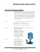
1 1 INTRODUCTION/INSTALLATION The miniAV®-X Automatic Viscometer The miniAV®-X Automatic Viscometer is designed to automate the timeconsuming sample testing and cleaning operations required for determination of kinematic viscosity in accordance with ASTM D445 specifications. The operator places the test sample(s) in small vials in the sample holder(s), enters sample identification information from the computer keyboard, and initiates testing with software keypad commands.
2 Measuring kinematic viscosity Kinematic viscosity is a measure of the internal resistance to flow of a fluid under gravity with the pressure head being proportional to the density of the fluid. For any particular viscometer, the time of flow of a fixed volume of fluid is directly proportional to its kinematic viscosity. Units of measure An accepted unit of kinematic viscosity is one centimeter squared per second, which is called one stoke.
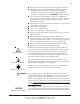
3 Make sure that your unit is operated only by qualified personnel. Make sure that you read and understand all operating instructions General Caution Hot Surface Caution and safety precautions listed in this manual before installing or operating your unit. If you have questions regarding instrument operation or documentation, contact CANNON® Instrument Company. Do not deviate from the installation, operation or maintenance procedures described in this manual.
4 AC Mains power cord must be attached to the connector labelled ~MAINS. This connection serves as a means of disconnect and should be readily accessible. (O) Supply OFF Symbol Hazardous materials The (O) symbol indicates the OFF position for the electrical switches for your unit (AC Mains or accessories). Routine miniAV-X operation may require the use and handling of hazardous chemicals and solutions.
5 6 77 88 99 10 10 11 11 12 7 Power Supply unit RS-232 serial cable DC Power cable Power cord Vacuum Pump unit power cable Exhaust tubing (1/4” blue opaque12 polyethylene) Mini DIN 4 cable To computer 5 7 To optional drying solvent (B) 5 1 12 4 User-supplied solvent vessel 4 4 to user ventilation system 11 Waste-Vac Ring To MAINS power 4 5 9 2 8 3 10 6 CANNON® miniAV-X Automatic Viscometer with VISCPRO® Instruction & Operation Manual Version 1.
6 CAUTION When moving or positioning the miniAV-X unit, do not lift it by the side panel units (“ears”). Hinges on these modular components are designed for easy removal. Always support the miniAV-X unit from the base. Vacuum Pump unit connections Use the 1/4” blue opaque polyethylene tubing to vent exhaust from the Waste Receiver Assembly Exhaust port to the user ventilation system. Use the 6 mm FEP tubing to connect the Vacuum Port to the bath unit Vacuum connector.
7 Installing VISCPRO ® software To install the VISCPRO® software, follow the instructions below in the sequence presented. Make certain that you complete the sections on checking instrument settings and initial calibration data. If you encounter difficulties at any stage in the installation process, call CANNON® service at 814-353-8000. Computer requirements Consult CANNON® Instrument Company at 814-353-8000 for current computer specifications.
8 Running the software the VISCPRO II icon Provide power to the miniAV-X instrument, and verify serial connections to the computer. To load your newly-installed VISCPRO® software, double-click on the VISCPRO® icon on your Windows® desktop (Windows® NT® users can click Start/All Programs/VISCPRO/VISCPRO 2.0).
9 The Sample Input window NOTE If the Sample Input window does not appear when the software loads, click View Instrument from the Main menu, then click the desired instrument group (type of instrument, e.g. miniAV-X, CCS, CAV-2100) from the list of available instruments and click OK. If the Available Instruments list box is blank, your miniAV-X instrument may not be on-line. Check cable connections and make certain the unit power switch is ON.
10 NOTE If you wish to restore the original configuration, archive your sample data before doing so (see Chapter 13 for information on using the Database Manager software). Then copy the original SAMPLES.MDB file from the CD-ROM to the database directory corresponding to your operating system (see table, previous page).
11 You will use the Instrument Settings window (see below) to describe and control miniAV-X instrument operational features. These settings affect the instrument as a whole. Check the instrument settings for your instrument per the instructions below, and make any necessary changes: The Instrument Settings window Use the ID field to input instrument identification information using up to 16 alphanumeric characters.
12 Viewing/editing setup information NOTE For first-time installation, make certain that the factory-prepared Configuration file has been copied to the Default Data directory per instructions on page 7 of manual. If your instrument has already been configured, you can use the instructions in this section of the manual to check or, if necessary, change the instrument settings. 1. Click Configure from the VISCPRO® menu bar. 2.
13 Manually changing tube calibration constants If you discovered any errors in the values of the calibration constants (see previous section), follow the directions in this section to manually correct them using calibration information previously obtained for your unit. If the calibration values are correct, instrument setup is complete. NOTE This procedure for manually entering/changing calibration constants bypasses the normal calibration procedure.
14 The Calibration window Compare this value to your archive of the calibration constant data (if available) for bulb 1. The values should be identical. 3. If they are not, place your cursor in the appropriate field, delete the entry, then type the correct values for the constant in the text box. 4. Click Update tube . 5. Use the bulb spin controls to select the other bulb(s) for which you noted calibration constant errors. Input the correct values for each.
15 Compare the values in the Tray Settings: Wash window with your archived values and make any necessary changes; then click OK. To check Advanced Settings for your miniAV-X instrument, click Configure from the VISCPRO menu options and select the desired instrument. Then click Tray Settings: Advanced. The Tray Settings: Advanced window will appear. CANNON® miniAV-X Automatic Viscometer with VISCPRO® Instruction & Operation Manual Version 1.
16 Compare the values in the Tray Settings: Advanced window with your archived values and make any necessary changes; then click OK. Preparing the miniAV-X for testing Inserting the miniAV-X temperature probes/reference thermometer Inserting the probes The temperature probe and thermal fuse probe are semi-permanently installed. Initial installation or replacement requires removal of the top cover of the bath unit.
17 NOTE If using the ERTCO-HART 12” temperature probe in place of the ASTM thermometer, it will be necessary to remove the grommet in the bath top cover prior to inserting the probe. The probe will seat properly in the aperture left by the grommet removal. Adjusting Vacuum/Pressure settings To adjust the vacuum setting for the miniAV-X, click Service from the VISCPRO menu options and select the desired instrument group and instrument.
18 3. Select the desired unit of temperature measurement (°C or °F). 4. Type the desired temperature in the Bath Temp: field. Acceptable values are any numbers between 20°C and 100°C. If necessary, you may use the decimal point key to input temperature to the nearest 0.01°C. Press OK to save the temperature setting. NOTES The miniAV-X will not allow sample testing until the instrument has equilibrated temperature at the test temperature.
19 Bypass .... option To begin washing an evacuated sample cup, click the option box to make certain that the Bypass initial cup evacuation option is selected. Do not use this option with a filled cup or the cup will overflow. 4. When the Wash cycle has been completed, click Done to exit the Wash viscometer tube window. NOTES CAUTION The Wash operation cannot be executed if the tube is currently running a sample. To terminate the Wash cycle at any time, click Abort Wash.
20 This page intentionally left blank. CANNON® miniAV®-X Automatic Viscometer with VISCPRO® Instruction & Operation Manual Version 1.
21 CHAPTER 2 TESTING SAMPLES WITH THE miniAV-X AUTOMATIC VISCOMETER This chapter of the manual will provide information on testing samples using the miniAV-X. Observe the safety cautions noted in the introductory chapter when operating equipment. The miniAV-X should only be operated by qualified personnel. Turning on the miniAV-X Turn on the miniAV-X Bath Unit using the power switch on the power supply unit. Testing samples Loading software NOTES 1.
22 4 Check the thermometer in the temperature bath to make sure the bath is holding the proper temperature. If necessary, calibrate the miniAVX temperature control probe using the temperature calibration procedure in Chapter 3. 5. Open the View Instrument Group window (if it is not already open) by clicking View Instrument from the Main menu and selecting the desired instrument group from the list box (see Chapter 4 for more information). The View Instrument Group window 6.
23 Then click the Tray tab corresponding with the desired miniAV-X. 7. Double-click on Sample ID (1) with the left mouse button to access the sample ID data entry field (or press 2). 8. Enter sample ID information in the sample list box using your computer keyboard. After you have typed the sample ID, press the T key to complete the entry and move the cursor to the next Sample ID field. Or press R to complete the entry.
24 Pausing a test To temporarily halt testing for a given tube/sample, click the Pause button from the Sample Input window. Then select the desired tray (miniAV-X instrument) and pause action(s) from the Select Trays window (Pause Now will immediately pause test actions; Pause after current sample will pause testing after the current test is complete). Click OK to pause testing for the selected tray(s).
25 To review status of other online instruments, click the tube tab corresponding to the desired instrument (see next section). If necessary, wipe any excess oil from the base of the miniAV-X, sample vial and vial holder using an absorbent paper towel. If necessary, clean these components before reuse by wiping with a paper towel wetted with appropriate solvent. Working with Instrument Groups VISCPRO II provides a convenient interface for working with multiple CANNON instruments simultaneously.
26 You can toggle back and forth between the Sample Input window and the new instrument group Machine Status window by pressing CtrlPage Down. Monitoring instrument status You can monitor the status of all instruments in an instrument group by pressing Ctrl-Page Down from the Sample Input window to display the Machine Status window. To return to the Sample Input window, press Ctrl-Page Down again.In the image above, instruments three and four do not exist but could be accommodated in this instrument group.
27 NOTE Do not use “0” or “9” as an instrument address for this configuration option. When configured per the above instructions, the instruments will always be displayed in the same “sequence” in the Machine Status window even if a single instrument in the series is not online. Viewing test results Data obtained from all miniAV-X instruments during sample testing is promptly displayed in the Sample Input window (Sample Action column). It is also stored in the central VISCPRO® database.
28 8. Click on the spin controls to select a value for the sample time window (the time parameter you desire for the report of recent test data). 9. Configure any other report options (see Chapter 7 for details). Then click OK. The program will prompt you to save the analysis configuration. 10. Click Yes. (OR click NO to display the analysis without saving it.) 11. If Yes was selected, use your keyboard to type the name you wish to use for the analysis in the text box. 12. Click OK.
29 CHAPTER 3 CALIBRATING THE miniAV-X Calibration is essential for the proper operation of the miniAV-X. The miniAV-X is calibrated before it is shipped to the customer. It should be calibrated again after installation. Frequency of recalibration is at the discretion of the user.
30 The entered actual temperature must not cause a correction in temperature greater than +/- 5.0 degrees. Click the Service/Zero Temperature Offsets menu item and select which offsets to clear. Multiple corrections Multiple or successive entries of correction for any temperature are permissible. A newly entered corrected temperature is mathematically compensated with the previously entered correction and is stored in memory by the onboard microprocessor as the latest correction.
31 Select the desired training parameters as follows: Trip Points Only option: Click the Trip Points Only option to adjust the sensor trip points without setting the voltages. This is useful if it is neccessary to adjust trip points on sensors for which voltages have already been set. After selecting the desired training options click START and follow the software prompts to complete the sensor training.
32 NOTE CAUTION If a check standard viscosity has NOT been entered (or if the default viscosity value of 1.000 has not been accepted by the user), a yellow arrow (current sample) or red circle caution symbol will appear to the left of the sample ID: Make certain to enter the correct check standard viscosity (in centistokes) BEFORE running the standards. Incorrect data entry may skew future calibration results. 5. Click Run, then select the appropriate sample trays to test the standards. 6.
33 The miniAV-X Calibration window 9. Use the spin controls to select the desired Bulb for calibration. Selecting samples 10. Select (or deselect) the specific sample entries you desire to use for calibration from the displayed list by clicking on them. To select a range of samples, highlight the first sample and click on the last sample while simultaneously pressing the S key. To select several individual samples for calculation, hold down the C key and click on each of the desired samples.
34 If the difference is still too great, repeat the calibration process until the difference falls within acceptable limits (refer to the precision statement in ASTM D 446). If the tube calibration fails repeatedly, refer to Chapter 5 for miniAV-X maintenance/service information. 12. When the new calibration constants are acceptable, click on Update tube to save the constants for the current instrument.
35 In the miniAV-X, viscosity is calculated by using the viscosity calculation equations as described in ASTM Methods D445 and D 446. Because samples running in the miniAV-X can have short flow times, the kinetic energy correction term (E / t2) is used as prescribed in the aforementioned ASTM methods. The VISCPRO® software for Windows® performs all necessary calculations to derive constants C and E.
36 This page intentionally left blank. CANNON® miniAV®-X Automatic Viscometer with VISCPRO® Instruction & Operation Manual Version 1.
37 CHAPTER 4 USING THE miniAV-X SOFTWARE VISCPRO ® generic instrument interface Your software for Windows® is comprised of a generic instrument interface (VISCPRO®) and a collection of instrument/analysis-specific modules. This chapter of the manual will explain the software options for the VISCPRO® program and other modules commonly bundled with the instrument software.
38 Main Menu The View Instrument menu item opens the View Instrument Group window which permits you to select the desired test instrument type from the list of on-line instruments. The View Instrument Group window The View Instrument Group window is comprised of: The Instrument Group list box Three button options (OK, Cancel, and Help). View Instrument Group window button options: Opens the Sample Input window for the selected instrument group and restores any configuration settings for that group.
39 The Poll for Instruments menu item queries the hardware interface to establish communications with CANNON® instruments attached to the host computer. Use Poll for Instruments to establish a computer connection with instruments which may have come “on line” after the software has been in operation. When the connection has been verified by the controlling software via the hardware interface, the instrument name will be added to the status bar at the bottom of the VISCPRO® window.
40 2. Select the desired name from the drop-down list box. 3. Type the password in the Password field for the individual selected. 4. Click OK. Use the Change Password feature to change the current user password. Procedure 1. Log in to the VISCPRO® software using the Log In command from Main. 2. Select Change Password from the Main menu options. 3. Type in the new password in the Password field. 4. Retype the password in the Confirm Your New Password field. 5.
41 To use the Log Out feature, click Log Out from Main. The current user will be logged out of the security list of authorized miniAV-X technicians and managers. The software will automatically reset to the lowest security level. Any ongoing test operations will continue. Adjusting Security Settings VISCPRO® provides an interface to customize security settings for your facility. To adjust the security settings for your VISCPRO® software, complete the procedure below: 1. Log in as a Manager. 2.
42 Print/Print setup menu items Select this standard Windows® print menu item to access the Windows® print window. Then select print options for the currently-active analysis/ report (see Analysis options). Select this standard Windows® print menu item to access the print setup window. Check your printer driver documentation for additional information on print setup options. Select the Exit option to exit ViscPRO. Or you may click application title bar.
43 View Analysis—opens the Choose Analysis window. See View Analysis, below, for more details. Report Title—opens the Designate Report Title window. Permits data entry of up to three lines of text for the report title. Configure Analysis—Accesses Configuration options. For information on configuring analyses, consult Chapter 6 and the manual chapter corresponding to the particular analysis. Save Configuration—Opens the Save Configuration window.
44 Click the appropriate radio button . Then select the desired saved configuration (if any) and click OK: Select Open Selected Radio button options for analysis configuration Analysis Configuration if you wish to create and display the selected analysis using the saved configuration highlighted in the list box on the right side of the Choose Analysis window.
45 group button on the status bar on the bottom of the primary window. Restoring a saved window configuration does not affect current miniAV-X sample testing operations. miniAV-X module menu options In addition to the VISCPRO® general instrument menu functions, unique software application modules for each type of CANNON® instrument generate additional interface options. The modules determine the characteristics, function and appearance of VISCPRO® software menus and windows.
46 or Cancel to exit the Save Calibration Data window without saving the information. The calibration certificate will be printed after you exit the Save Calibration Data window. CANNON Instrument Company recommends saving instrument and tray settings each time a new calibration is performed.
47 The Restore Configuration window This is a security-protected feature. Depending on the user-set configuration options, technician-level personnel may only be able to restore Sample ID information. Individuals logged in to VISCPRO as a Manager will be able to restore Instrument Settings and Tray Settings. To restore information, click on the check boxes corresponding to the desired parameters. Then click OK.
48 The S/N: field displays the instrument serial number stored by the operational firmware of the miniAV-X. This is a non-editable field. The miniAV-X Instrument Settings window Click on this check box to activate a software counter which will generate a warning for a tube whenever the specified number of days have elapsed without performance of the Verify Known KV sample action. Enter the number of days in the appropriate field.
49 Instrument Settings window button options: saves the current instrument settings and exits the Instrument Settings window. restores the default configuration settings for several instrument options closes the Instrument Settings window without saving any configuration changes. Tray Settings: Tube and Bath Use the Tray Settings: Tube and Bath window to describe and control test parameters for the viscometer tube. Alter the settings using the instructions below.
50 NOTE For reporting and calibration purposes, each tube serial number value should be unique for all instruments attached to a single computer. Click on the Fast Run Tube check box if the viscometer tube is the fast run type. The Wet Tube option is required for some viscosity determination protocols. If this option is checked, the miniAV-X automatic determination will be preceded by an untimed sample drop, coating the inside of the capillary with the sample material.
51 Soak time Input the desired sample soak times for each bulb of the viscometer tube. The soak time is the length of time in which the sample will remain in the viscometer tube before being dropped. The soak time is important to ensure temperature equilibration of the sample. The range is from 0 to 240 based on which units of time the user selected from Soak Time Units. Constants The Tray Settings: Tube and Bath screen displays the calibration constants (C and E) for each bulb of the viscometer tube.
52 Enter the maximum acceptable difference in measured results when using multiple determinations (the default percent difference value is 0.35 percent and the default absolute difference value is 0.2 seconds). Use greater If both tolerance options are selected, the VISCPRO software will apply both criteria unless the Use greater option is checked. If Use greater is checked, then the software will apply the less exacting tolerance value when calculating/evaluating test results.
53 Selecting sample run required and maximum determination settings Select the number of Required determinations by clicking on the spin controls (values from 1 to 4 are acceptable). In the same manner, select the Maximum number of determinations which can be run for the tube samples (values from 1 to 20 are acceptable). NOTES VISCPRO determines the sample flow time by averaging the values of the sample runs which correspond to the chosen criteria.
54 The Tray Settings: Wash window Solvent rinse settings The solvent rinse settings for Solvent A and (if applicable) Solvent B are determined using the Tray Settings: Wash window. Select a value from 0 to 18 cycles for this option (the “0” setting turns the solvent option off). These settings determine the number of rinse cycles performed by the miniAV-X instrument after each test. Higher viscosity materials may require more rinses.
55 Solvent flush time(s) The Solvent flush time(s) setting determines the amount of time (in seconds) that the solvent pump will continue to operate after the solvent chamber has emptied all solvent into the sample vial during a wash. This allows time for the lines and viscometer tube to be purged of solvent. Select a value from 1 to 60 seconds for this option. The time will vary with the pressure setting (miniAV-X right front “ear” panel).
56 NOTE When you have completed the configuration and saved the current wash settings, you may wish to permanently store the current instrument settings using the Save Instrument and Tray Settings. Tray Settings: Advanced Select the Tray Settings: Advanced menu item to open the Tray Settings: Advanced window used to define additional operational parameters for sample testing with the miniAV-X instrument. It may be necessary for you to log in as a Manager to access Advanced settings.
57 Min. bulb 1 selection time(s): Adjust this setting to select the desired minimum time permitted for selection of bulb 1 or bulb 2 for sample testing. Acceptable values are between 0 and 20 seconds. Decreasing the setting will increase the probability that the sample will be tested in bulb 1.
58 Select which bulb to apply the Vent bulb drain time parameter. Bulb overdraw Use the Bulb Overdraw button/window to set the the amount of time in seconds that the instrument will draw sample AFTER the sample meniscus has covered the target sensor in the viscometer tube. More viscous materials may require a larger overdraw time to ensure that the sample meniscus does not dip below the target sensor during temperature equilibration.
59 Date selection: The calibration program uses data from previously-run standards to determine the calibration constants. To select the desired standard data, use the No older than [x] days spin controls to set the date parameters for the database search (if “1” is selected, only the standards run in the past 24 hours will be used). Bulb selection: Viscometer bulbs are numbered from the bottom to the top of the viscometer tube. Use the spin controls to select the correct bulb for calibration.
60 The Calibration window NOTE You must click Update tube before changing bulbs if you wish to save the new calibration constants for that bulb. If you close the Calibration window without updating the tube, the new calibration information will not be saved. Service menu To access the service menu items, click Service from the VISCPRO® primary display and select the desired instrument. The Monitor window permits the user to view current operational values for the miniAV-X instrument.
61 When the Wash cycle has been completed, click Done to exit the Wash viscometer tube window. NOTES CAUTION The Wash operation cannot be executed if the tube is currently running a sample. To terminate the Wash cycle at any time, click Abort Wash. The Wash viscometer tube function overrides automatic miniAV-X software operations. Verify that the tubes are clean and dry before initiating computer-controlled sample testing.
62 To calibrate for temperature, see Chapter 3 for details. Temperature calibration requires a reference thermometer with an accuracy meeting the precision specification of ASTM D445. To zero temperature offsets, click the Service/Clear Temperature Offsets menu option for the desired instrument. The Zero Temperature Offsets window will open. Click the check box to select each desired action. Then click OK to clear the selected settings.
63 the Clear General Offset option is checked, VISCPRO will clear the (factory-preset) General Offset for all temperatures for the instrument. This Instrument Setting cannot be restored except from a previouslysaved Configuration. It is not recommended that you exercise this option without consulting with CANNON Instrument Company personnel.
64 with CANNON Instrument Company personnel if problems with sensor training persist. To set security levels, first log into the VISCPRO software as a Manager.
65 When you have finished updating settings, click the Save button to save settings and close the Set Security Levels window. Or click Cancel to close the window without saving changes. Testing samples—software options This section of the manual provides information on using the software to perform common miniAV-X operations. For a step-by-step procedure detailing both hardware and software operations involved in sample testing, refer to Chapter 2. Entering sample ID information Procedure 1.
66 Sample actions No action—clears action column for highlighted samples. No testing The Sample Action popup Viscosity Action window will take place for this tray position. Measure kinematic viscosity—measures sample viscosity. Verify Known KV—measures sample viscosity at the conclusion of the automated test and tags data for possible use in calibrations/ reports.
67 Sequential Sample IDs—creates a numeric sequence for the highlighted sample ID(s) in the list box. You have the option of selecting a standard alphanumeric prefix and/or suffix to accompany the sequence numbers, and you also can select the starting numeral in the sequence. Procedure 1. To use the Sequential Sample IDs feature, highlight the desired sample tray location(s) in the list box (or skip to the next step to select all). 2.
68 The viscosity of the standard must be entered in the Check Standard Viscosity field in order that the resultant viscosity determination may be used for verification and calibration. Copy & Paste Sample ID data entry options The VISCPRO® Sample ID data entry screen supports Copy and Paste options. Copying Sample IDs To copy a Sample ID entry, including the configuration information, highlight the desired line(s) from the Sample List Box and right-click your mouse to access the Sample Action window.
69 lighted sample (or samples) will be deleted and any existing sample entries following the removed items will be moved up to take their place in the sample run sequence. Saving Sample ID information Many users will test the same series of samples on a regular basis for trend analysis and other quality control objectives. To save time with Sample ID data entry, VISCPRO provides an option for saving and recalling Sample ID information.
70 The Load Instrument and Tray Settings option permits you to restore the following Tray Settings: Tube S/N, tube type, wet tube option, bath temp, and tube calibration constants. Click the name of the desired confiugration to highlight it. Then click OK. Selected settings will be restored. The Load Instrument and Tray Settings window miniAV-X analysis modules The VISCPRO® software is shipped with several analysis modules which can be used to create reports based on sample test data.
71 with matching Sample IDs. If samples with an identical Sample ID have been tested on a low temperature tube and a high temperature tube within an 8-hour time span, the VI for those samples can be calculated and displayed on the VI analysis. The VI Matching function is always indicated on the VISCPRO® status bar, whether or not a VI domain (viscometer tube set) has been defined. Configuration procedure To configure the VI Matcher: 1. Load the VISCPRO® software. 2.
72 6. Click on the serial numbers in the Select Low Temperature Tubes list box which correspond to tubes that should be configured as low temperature tubes by the VI Matcher. As you do so, the serial numbers will be added to the Selected Tubes list box. NOTE Samples must have been previously run in a tube in order for the tubes to show up in the Select Tubes list boxes To “de-select” a selected tube, click again on the highlighted tube serial number 7.
73 CHAPTER 5 OPERATING, MAINTAINING AND SERVICING THE miniAV-X This chapter of the miniAV-X Instruction & Operation Manual contains information regarding the operation, service and maintenance of the miniAV-X instrument. For additional information on required utilities, instrument installation and setup, refer to Chapter 1.
74 Bath Unit connections For information regarding Bath Unit connections, refer to the installation section of Chapter 1. Solvent Dispensing System The miniAV-X is equipped with a solvent system used to wash the viscometer tubes after each sample test. The system consists of the internal and external solvent and drain lines, the user-supplied solvent vessel, and the Waste Receiver assembly (including solvent dispensing unit).
75 Application compatibility The solvent used in a particular viscometer tube must be able to dry at the test temperature of the tube (during the washing cycle). Choose the appropriate solvent accordingly. Checking solvent levels It is the responsibility of the operator to visually monitor the amount of solvent remaining in the solvent container. Check the solvent container liquid level frequently. When the solvent level drops to within 2.5-5.
76 WARNING Waste sample/solvents can present possible environmental and health hazards. Dispose of all waste materials in accordance with environmental and safety regulations. Dual-solvent washing For testing heavy or hard-to-clean materials, CANNON® Instrument Company recommends a dual-solvent washing system. The dual-solvent washing process uses two different solvents. The first wash might ordinarily use a heavy solvent to clean the sample residue out of the viscometer tubes.
77 Carousel Adjustments Homing the Carousel 1. From the Service menu in ViscPRO, select miniAV-X Motor Control. 2. Check Home Motors. 3. Click Start. 4. The carousel will home itself. NOTE Factory Preset refer to the instructions below only if out of Adjustment. Adjusting sample tray height 1. Ensure the R208 driver units have been properly adjusted and the power is off. 2. Open the motor driver housing and connect a multi-meter to GND and EHOME. 3.
78 4. Apply power to the instrument and adjust the potentiometer to get a reading of 0.50V for the elevate driver. 5. Turn off the power to the instrument. 6. Disconnect the positive probe from the potentiometer lead of the elevate driver.7. Connect the positive probe to the potentiometer lead of the rotate driver. The rotate driver is located furthest from the instrument. 7. Apply power to the instrument and adjust the potentiometer to get a reading of 0.34V for the rotate driver. 8.
79 3. Fill the bottle with silicone fluid and screw the Fill Cap Assembly onto the bottle. Ensure that the breather tube is positioned with the tube opening at the bottom of the bottle. 4. Insert the end of the fill tube from the Fill Cap Assembly into the slot in the top of the bath flange. Slot for fill tube insertion 5. Lift and invert the bottle to begin introducing 900 mL of the appropriate grade of ambient-temperature silicone bath fluid into the bath. Add a small amount first and check for leaks.
80 4. Loosen the drain plug on the side of the bottom bath flange using the supplied 3/16” hex driver. Fluid should begin draining from the bath into the storage container. 5. When fluid has drained from the bath, close the drain valve by tightening the drain plug clockwise to its furthest position. Tighten securely to prevent leaks. 6. Remove the drain hose from the drain tube. 7. Replace the front panel with the screws previously removed. Then close the ear panels to complete the drain procedure.
81 Ventilation The miniAV-X requires installation of the supplied 3” ventilation hose to the exhaust shroud on the rear panel of the unit. The shroud must be connected to a customer-supplied exhaust fan/ventilation system. A 3”-4” hose adapter is shipped from CANNON Instrument Company with each miniAV-X unit. The air flow rate and design of the exhaust fan must be suitable to handle the vapors from the customer-supplied solvent and samples.
82 4. After the tube has been washed, click Done to close the Wash Viscometer Tube window. Setting wash parameters For information on using the computer to select wash parameters, see Chapter 4. Preventive maintenance The miniAV-X is a precision instrument, durably crafted for years of trouble-free operation.
83 miniAV-X repair/replacement components The parts included in the list below are the more common repair/replacement components for the miniAV-X. When making repairs using these items, make certain to replace obsolete or worn components with matching components. Installation kit The installation kit contains all parts required for assembly/installation of the miniAV-X. Kit replacements may be purchased from CANNON® (part #P81.2229).
84 This page intentionally left blank. CANNON® miniAV®-X Automatic Viscometer with VISCPRO® Instruction & Operation Manual Version 1.
85 CHAPTER 6 ANALYSIS CONFIGURATION OPTIONS Data obtained from all instruments during sample testing is stored in the central VISCPRO® database. To view data, you must create an analysis configuration requesting the desired sample information in the desired format. Analysis configurations can be saved and later restored. The analysis configuration options provide powerful tools for reporting sample information.
86 NOTE If you have already configured and saved an analysis, its name will appear in the list box on the right side of the window. If you click on an existing configuration and click OK, the analysis will be performed using the selected configuration settings. It will not be necessary to complete the remaining steps in this procedure. 5. Click OK. The analysis Configuration window will appear. The Configuration window consists of tabbed pages with filter options appropriate for the analysis. 6.
87 Using the date filter Use the date filter to select date/time parameters for the analysis. To use the date filter, click the Date Filter tab from the analysis configuration window. To define a Fixed Date and Time, click the corresponding radio button . Then use the spin controls and/or list box selection options to set the appropriate date/time parameters. All samples tested after the start date/time and before the end date/time, inclusive, will be included.
88 Using the sample filter Use the sample filter to limit the analysis to samples which have been tested on certain instruments and tubes, or which have certain Sample ID characteristics. To filter samples by instrument, tube serial number (S/N) or Sample ID, click the Sample Filter tab from the analysis configuration window. Some (not all) analyses offer an option to display data for samples which did not complete successfully. Click the Display Unsuccessful Samples box if you wish to use this data.
89 include data from all samples starting with S. %S% would include data from all samples containing S. The underscore (_) is a single-character wildcard. You may use multiple IDs separated by a comma. For example, AV%,40C% would display all samples beginning with AV or 40C. NOTE If no instruments/tubes/Sample IDs are selected, the analysis will display data for ALL instruments/tubes/Sample IDs.
90 Saving a current analysis To save a current analysis configuration: 1. Select Analyses from the VISCPRO® primary menu options. 2. Select Save Analysis from the Analyses menu options. 3. Select the desired analysis. The Save Configuration window will appear. Type the name of the new configuration in the Save As: field. Or double-click the name of a preexisting configuration in the Existing Configurations list box to replace the existing configuration with the new configuration settings. 4. Click OK.
91 Keystrokes for selecting data for printing You can print data for a selected sample or samples from an on-screen analysis by highlighting the desired sample data and then using the Print option from the VISCPRO® Main Menu. To select data for a single sample, click on the line of data associated with the sample on the screen display. To print a sequential range of samples, highlight the first sample in the range, then hold down the S key and click on the last sample in the range.
92 This page intentionally left blank. CANNON® miniAV®-X Automatic Viscometer with VISCPRO® Instruction & Operation Manual Version 1.
93 CHAPTER 7 CAV DATA TABLE The CAV sample analysis is designed to permit convenient viewing of data collected from samples which have been tested using the Measure Sample Viscosity sample action option. The sample analysis displays sample data in a tabular format.
94 {1,10} Efflux%—For multi-drop samples: displays the first 10 sample efflux times {1,20} Efflux%—For multi-drop samples: displays the first 20 sample efflux times Avg Efflux%—The average efflux time for efflux values used for viscosity calculation C, E—The calibration constants used for this determination SUS—Saybolt Furol Seconds calculation % KE—Percent contribution of the kinetic energy correction to the measured viscosity.
95 The Choose Analysis window 5. Click on the Define and Open New Configuration radio button (or verify that the option is selected). NOTE If you have already configured and saved an analysis, its name will appear in the list box on the right side of the window. If you click on an existing configuration and click OK, the analysis will be performed using the selected configuration settings. It will not be necessary to complete the remaining steps in this procedure. 6. Click OK.
96 Date/Sample filters Complete selection of Date/Sample filter options per the instructions in Chapter 6. Report filter To select data for inclusion in the Analysis, click the Report tab. Then select which fields to include in the report by clicking the “Click here...” box and selecting the desired data from the dropdown list. After individual options have been selected, review the default settings for Precision, Format and Units [of measure].
97 8. When you have completed the configuration, click OK. The program will prompt you to save the configuration. 9. Click Yes to save the configuration. The Save Configuration window will appear. The Save Configuration window 10. Type the name of the new configuration in the Save As: field. Or double-click the name of a preexisting configuration in the Existing Configurations list box to replace the existing configuration with the new configuration settings. 11. Click OK.
98 This page intentionally left blank. CANNON® miniAV®-X Automatic Viscometer with VISCPRO® Instruction & Operation Manual Version 1.
99 CHAPTER 8 STANDARD VI TABLE ANALYSIS The Viscosity Index (VI) matching sample analysis displays VI data from samples which have been tested using the Measure Sample Viscosity sample action option and matched according to user-defined criteria. The VI analysis displays sample data in a tabular format.
100 The Choose Analysis window 4. Select Standard VI Table from the VI Package report options. 5. Click on the Define and Open New Configuration radio button (or verify that the option is selected). NOTE If you have already configured and saved an analysis, its name will appear in the list box on the right side of the window. If you click on an existing configuration and click OK, the analysis will be performed using the selected configuration settings.
101 Date/Sample filters NOTE VI Analysis filter Complete selection of Date/Sample filter options per the instructions in Chapter 6. The VI Matcher does not match invalid samples UNLESS the Allow Matching ... box from the Sample Filter tab options is checked. The VI Matcher never matches unsuccessful samples (samples with no flow time and a displayed kinematic viscosity of “0”).
102 9. Click Yes to save the configuration. The Save Configuration window will appear. Type the name of the new configuration in the Save As: field. Or double-click the name of a preexisting configuration in the Existing Configurations list box to replace the existing configuration with the new configuration settings. 10. Click OK. The analysis will be performed and displayed using the selected configuration settings.
103 CHAPTER 9 SAMPLE DATA EXPORT ANALYSIS The VISCPRO® Sample Data Export analysis provides a convenient operator interface for configuring sample information from the sample database for serial output and exporting it in ASCII text format. The port output filters (Date, Sample and Port Output Format) permit the user to select and output desired data to a file, LPT port or serial port in whatever format is desired.
104 Configuring the Sample Data Export analysis 1. Select Analyses from the VISCPRO® menu options. 2. Select View Analysis from the Analyses menu options 3. Double-click Data Export Package from the list of available analysis types. 4. Select the Sample Data Export analysis option. 5. Click the Define and Open New Configuration radio button define a new analysis configuration.
105 The Port Output Format window NOTE If you select NEW FILE for output, click the button to open the Windows Save As: box. Select the desired directory and type the desired file name in the File Name: text box. If you select an existing file, ASCII port analysis data will be appended to the file. Make certain that you have selected the desired port for configuration by clicking on the port name in the Add Port list box prior to selecting output data and formatting options for that port.
106 f. NOTE Click the buttons corresponding to the data types you wish to output on the report. As you do so, the appropriate coding for the output analysis will be inserted in the text box. For some data output options, you will need to select the desired output field length using the spin controls provided in the Format Data Output window. Experienced users may type code directly into the text box by placing the cursor at the appropriate point.
107 existing configuration with the new configuration settings. Then click OK. The saved analysis will be displayed using the selected configuration settings, and the data will be sent to the selected ports. NOTES You may click Cancel from the Save Configuration window to exit without saving configuration changes. The Port Output Analysis cannot be reconfigured. This avoids duplication of output data for collection devices your facility may have in place.
108 This page intentionally left blank. CANNON® miniAV®-X Automatic Viscometer with VISCPRO® Instruction & Operation Manual Version 1.
109 CHAPTER 10 VI DATA EXPORT ANALYSIS The VISCPRO® VI Data Export Analysis provides a convenient operator interface for configuring Viscosity Index (VI) sample information from the sample database for serial output and exporting it in ASCII text format. The port output filters (Date, Sample and Port Output Format) permit the user permit the user to select and output desired data to a file, LPT port or serial port in whatever format is desired.
110 Tech 1/Tech 2—Technician name (the individual logged in at the time the sample run was completed) for the low/high temperature sample ASCII Codes—Permits addition of user-selected ASCII codes to analysis Space—Inserts a blank space (formatting option) CR—Inserts a carriage return code (formatting option) LF—Inserts a line feed code (formatting option) Next/Previous—Displays more button options Configuring the VI Data Export Analysis 1. Select Analyses from the VISCPRO® menu options. 2.
111 VI Port Output Format options Adding ports c. Click Add Port from the Port Output Format button options to open the Select Port window. Select the desired serial port(s) and/or files for output and verify the configuration settings for each. Then Click OK. Added ports will be displayed in the port list box. NOTE If you select NEW FILE for output, click the button to open the Windows Save As: box. Select the desired directory and type the desired file name in the File Name: text box.
112 d. Select the desired port/file for configuration by clicking the name of the port/file in the port list box. Then click the radio button corresponding to the desired locale format (U.S. or local). Your choice will determine the formatting of numeric data and dates. Delaying serial output e. You may delay data transmission of serial output for a time parameter you specify by clicking the Delay button to insert the delay code into the Configuration list box, Header or Footer.
113 9. If you do not wish to save the configuration, click No. The analysis will be displayed and the data will be sent to the selected ports. If you wish to save the configuration, click Yes. The Save Configuration window will appear. Type the name of the new configuration in the Save As: field. Or double-click the name of a preexisting configuration in the Existing Configurations list box to replace the existing configuration with the new configuration settings. Then click OK.
114 This page intentionally left blank. CANNON® miniAV®-X Automatic Viscometer with VISCPRO® Instruction & Operation Manual Version 1.
115 CHAPTER 11 ERROR DATA EXPORT ANALYSIS The VISCPRO® Error Data Export analysis compiles error information from the sample database for serial output and exports it in ASCII text format. The port output filters (Date, Error and Error Report) permit the user to select and output desired data to a file, LPT port or serial port in whatever format is desired. NOTE Available data for analysis Once the port output analysis has been generated, it cannot be reconfigured like other VISCPRO® analyses.
116 5. Click the Define and Open New Configuration radio button define a new analysis configuration. NOTE to If you have already configured and saved an analysis, its name will appear in the list box on the right side of the window. If you click on an existing configuration and click OK, the analysis will be performed using the selected configuration settings. It will not be necessary to complete the remaining steps in this procedure. 6. Click OK. The Port Output Configuration window will appear.
117 The Error Page tab You may use multiple IDs separated by a comma. For example, AV%,40C% would display all samples beginning with AV or 40C. NOTE Port Output Format filter Adding ports If no error sources/technicians are selected, the analysis will display data for ALL error sources/technicians. c. To adjust other analysis configuration options, click the Port Output Format tab (see Figure, next page): Click Add Port from the Port Output Format button options to open the Select Port window.
118 Error Ports Ouput Configuration options Delaying serial output e. You may delay data transmission of serial output for a time parameter you specify by clicking the Delay button to insert the delay code into the Configuration list box, Header or Footer. The Delay Configuration window will appear. To set the time of the Delay, type a numeric value in the appropriate field, and click on one of the radio buttons to select the correct unit of time. Then click OK. Selecting output data f.
119 Adding a header g. If you would like to include a header at the beginning of the analysis, click the Header button and add the desired text string via the keyboard. Format the entry as desired using the Carriage Return (CR) and Line Feed (LF) options as necessary to indicate line breaks. Then click OK. Adding a footer h. If you would like to include a footer at the end of the analysis, click the Footer button and add the desired text string via the keyboard.
120 Re-sending export data To re-send Port Output Analysis data for a displayed analysis, first save the analysis by clicking Analyses/Save Configuration, selecting the desired analysis, typing the analysis name in the Save As: list box and clicking OK. Then close the Port Output Analysis window and re-select Port Output Analysis by clicking Analyses/View Analysis from the primary menu options. Then click on the desired configuration from the list of saved configurations and click OK.
121 CHAPTER 12 ERROR LOG TABLE ANALYSIS The Error Log Table is designed as a troubleshooting tool to display error messages generated by the software during automatic processing of sample data. The Error Log Table displays data in a tabular format.
122 Choosing the Error Log analysis 4. Click on the Define and Open New Configuration radio button (or verify that the option is selected). NOTE If you have already configured and saved an analysis, its name will appear in the list box on the right side of the window. If you click on an existing configuration and click OK, the analysis will be performed using the selected configuration settings. It will not be necessary to complete the remaining steps in this procedure. 5. Click OK.
123 8. Click Yes to save the configuration. The Save Configuration window will appear. The Save Configuration window 9. Type the name of the new configuration in the Save As: field. Or double-click the name of a preexisting configuration in the Existing Configurations list box to replace the existing configuration with the new configuration settings. 10. Click OK. The analysis will be performed and displayed using the selected configuration settings.
124 This page intentionally left blank. CANNON® miniAV®-X Automatic Viscometer with VISCPRO® Instruction & Operation Manual Version 1.
125 CHAPTER 13 USING THE DATABASE MANAGER The Database Manager is a separate software program which is automatically installed in the same directory as your VISCPRO® software.
126 Starting the program To start the Database Manager software: 1. Exit the VISCPRO® application. Then click on the Windows® Start bar. 2. Select Programs/VISCPRO 2.0/VISCPRO Database Manager from the list of options. Archiving old data When to archive Data from the VISCPRO® database should be regularly archived in order to maintain the size and utility of the database file and to provide an additional level of security for your test data.
127 Change . . . procedure NOTE 1. Select Change Database Directory from the button options. A Browse … window will permit you to select the correct location for the database (SAMPLES.mdb) file. The current database directory is indicated at the top of the window. 2. Select the correct drive and use the Windows® controls to select the directory (folder) you wish to identify as the database location. 3. Click on OK to confirm database directory selection.
128 This page intentionally left blank. CANNON® miniAV®-X Automatic Viscometer with VISCPRO® Instruction & Operation Manual Version 1.
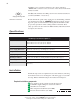
129 CHAPTER 14 REPLACEMENT PARTS LIST Following is a list of miniAV-X replacement parts available from CANNON® Instrument Company. Replacement fuses are initially provided with your instrument. It may be desirable for some users to maintain additional components in inventory. PART # DESCRIPTION P25.4030 P65.0149 P65.3013 P65.3245 P65.3247 P81.2100 P81.2102 P81.2108 P81.2109 P81.2111 P81.2113 P81.2150 P81.2162 P81.2164 P81.2185 P81.2194 P81.2198 P81.2199 P81.2217 P81.2218 P81.2219 P81.2236 P81.2238 P81.
130 This page intentionally left blank. CANNON® miniAV®-X Automatic Viscometer with VISCPRO® Instruction & Operation Manual Version 1.
131 CHAPTER A APPENDIX A–MULTIPLE UNIT CONFIGURATION Introduction The miniAV instrument is capable of being networked with the controlling computer via available RS-485 connections. As many as four miniAV instruments may be connected to a single computer. Follow the instructions in this appendix to complete assembly of the multi-unit networking kit, available from CANNON®.
132 4. Attach a shorter RJ-45 cable to one of the twin RS-485 connectors on the ear panel of the first miniAV bath. Then attach the other end of the cable to one of the twin RS-485 connectors on the ear panel of the adjacent Bath Unit. 5. Continue the procedure from the previous step for each bath consecutively until you have completed RS-485 connections between each Bath Unit and the previous unit in the sequence (see diagram). ------ ------ ------ 6.
133 CHAPTER I INDEX A D Abort test 24 Advanced configuration 56 Analyses 42 Analysis types 42 creating 87 deleting 92 menu options for 42 printing 92 printing selected data from 93 reconfiguring 91 resizing table columns for 91 saving 92 sorting data in 88 using the date filter for 89 using the report filter for 91 using the sample filter for 90 viewing 43 wildcard filter options for 90, 118 Analysis modules 71 ASTM methods 2 Available Instruments 38 Database Manager 127 archiving old data with 128 ch
134 O S (continued) Open Selected Analysis Configuration 44 Solvent container filling 77 Solvent Wash by computer 84 dual 84 Solvents 76 Spare parts kit 86 Standard ASCII Port Output analysis 105 adding a footer to 108 adding a header to 108 delaying serial output for 107 P Password changing 40 Pause 24 Poll for Instruments 39 Power supply 75 Preventive maintenance 21 R Repair/replacement kits 86 Restore Instrument Configuration 46, 59 Restore Sample Information 46, 59 Restore software options 45 T S