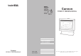
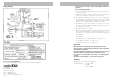
Cannon FITZROY FREESTANDING FREESTANDING MODELS FITZFS-SDSEB-NG FITZFS-SDSEB-LP USER INSTRUCTIONS Cannon FITZROY FREESTANDING INSTALLATION INSTRUCTIONS Part No: F2904 Revision D-2009 SERVICE INSTRUCTIONS This heater is approved for use with Natural and Propane gases.
Contents Contents 2 ❍ Distributor Warranty Safety warnings 3 4-5 ❍ What to do if you smell gas ❍ Warnings ❍ Standards User instructions 6-8 ❍ Operating instructions ❍ Flame characteristics ❍ Cleaning Heater specifications Installation instructions ❍ ❍ ❍ ❍ ❍ ❍ ❍ 9 10-15 Clearances Installation Gas connection Log installation Gas control Gas pressure point Installation tips Flue installation 16-17 ❍ Flue kit Service instructions ❍ ❍ ❍ ❍ ❍ ❍ ❍ ❍ ❍ ❍ ❍ ❍ 18-20 General To replace primary glass To re
Warranty 9. 10. 11. No gas to burner. Appliance lights but goes into lockout. Fuse blowing. • The gas valve should open at the same time as the igniter sparks. If there is no gas to the burner when this occurs check the solenoid coils for continuity. • Check that the gas pressure is present at the test point when the spark is being generated. • Check that there is gas to the inlet of the gas control.
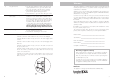
Safety warnings Please read this manual before installing and using the heater. What to do if you smell gas 1. Turn OFF the main gas supply. 2. Extinguish any open flame. 3. Open windows. Trouble-shooting. (Do not modify this appliance). To check the operation of the electronic (module) controller (Type 537 ABC) you will require a digital multimeter with the functions to measure AC/DC voltage, continuity, resistance and micro-amps.
Wiring diagram Do not spray aerosols in the vicinity of this appliance while it is in operation. Do not modify this appliance. 8. If removed, the glass window must be put back onto the unit prior to operating the heater. 9. Installation and repairs should be performed by a licensed service person only, refer to back of brochure for service number. 10. The appliance should be inspected prior to use, with regular inspections (annually) to be made by a licensed service person.
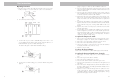
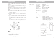
User instructions Operating instructions 1. Plug the power cord into the wall socket and turn on the power to the heater, see figure 1. Use of an extension cord is not recommended. 1 2. For control lay-out refer to figure 2. 2 page 11, figures 11 and 12, of the installation instructions. 2. Disconnect the fan plug from the plug carrier. Remove the two M5 wing nuts which locate the fan to the fan chamber underside. Lower fan from male thread. 3.
Service instructions. (Do not modify this appliance). General 1. Service work to be carried out by an authorised service person only. 2. Unplug from wall socket or turn off power at main switchboard if heater is hard wired. 3. Always shut off the gas supply and ensure that the heater is cool before commencing any service operations. 4. Always check for gas soundness after servicing. To replace the primary glass 1. Refer page 11, steps 9 to 11, of the installation instructions.
Flame characteristics The heater flames should be stable, not lifting from burner and the logs should glow after approximately 15 minutes operation on HIGH setting. The heater has been designed to burn with luminous flames, which mimic natural log combustion, and may exhibit slight carbon deposition. If heavy carbon deposits occurs or flames impinge on the roof of the combustion chamber, turn the appliance off and contact the service agent in your state.
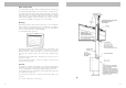
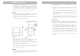
Flue installation This heater is a flued appliance. It must be properly connected to a flue system in accordance with the latest edition of the Gas Installation Code, AS 5601. If elbows are required, we recommend 45° only and no more than two in the total flue run. There should also be a minimum of 250mm straight flue section in between bends. If practical, locate the heater in a position to minimise the need for elbows. There must be at least 1.8m of vertical before any changes in direction of the flue.
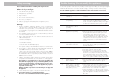
Installation instructions 1. This appliance is to be installed by a licensed service person only. 2. This appliance shall be installed in accordance with the manufacturer’s installation instructions, local gas fitting regulations, municipal building codes, electrical wiring regulations, and AS5601 the Australian Standard for gas installations. Refer also to AS5601 for pipe sizing tables. THIS HEATER IS NOT INTENDED FOR FIRE PLACE INSERT. Clearances 3.
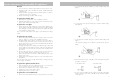
Gas pressure point 18 The pressure point is closed with a captive screw. Turn screw 6 revolutions anticlockwise to open the pressure point as indicated on figure 23 (a) and place manometer tube over the test point as per figure 23 (b). 8. Remove the pedestal front by unscrewing two screws either side. Refer figure 11. 23 11 19. Switch the top two control buttons to “Full On” position as indicated in figure 24(a) and using a ring spanner, as per figure 24(b), adjust the pressure to 0.
Gas connection 12. Connect incoming gas supply pipe to /2” compression fitting at rear of appliance. For inlet position see figure 15. 1 Advise the user in the operation of the heater. d) Place log No. 4 on single right back pin, ensure left side of log rests on depression in No. 3 log. Refer figure 20. 15. Refit the inner glass, but do not overtighten the screws. 16. Refit the heater front. 20 Gas control 17. Gas control layout is as indicated in figure 21.
Gas connection 12. Connect incoming gas supply pipe to /2” compression fitting at rear of appliance. For inlet position see figure 15. 1 Advise the user in the operation of the heater. d) Place log No. 4 on single right back pin, ensure left side of log rests on depression in No. 3 log. Refer figure 20. 15. Refit the inner glass, but do not overtighten the screws. 16. Refit the heater front. 20 Gas control 17. Gas control layout is as indicated in figure 21.
Gas pressure point 18 The pressure point is closed with a captive screw. Turn screw 6 revolutions anticlockwise to open the pressure point as indicated on figure 23 (a) and place manometer tube over the test point as per figure 23 (b). 8. Remove the pedestal front by unscrewing two screws either side. Refer figure 11. 23 11 19. Switch the top two control buttons to “Full On” position as indicated in figure 24(a) and using a ring spanner, as per figure 24(b), adjust the pressure to 0.
Installation instructions 1. This appliance is to be installed by a licensed service person only. 2. This appliance shall be installed in accordance with the manufacturer’s installation instructions, local gas fitting regulations, municipal building codes, electrical wiring regulations, and AS5601 the Australian Standard for gas installations. Refer also to AS5601 for pipe sizing tables. THIS HEATER IS NOT INTENDED FOR FIRE PLACE INSERT. Clearances 3.
Flue installation This heater is a flued appliance. It must be properly connected to a flue system in accordance with the latest edition of the Gas Installation Code, AS 5601. If elbows are required, we recommend 45° only and no more than two in the total flue run. There should also be a minimum of 250mm straight flue section in between bends. If practical, locate the heater in a position to minimise the need for elbows. There must be at least 1.8m of vertical before any changes in direction of the flue.
Flame characteristics The heater flames should be stable, not lifting from burner and the logs should glow after approximately 15 minutes operation on HIGH setting. The heater has been designed to burn with luminous flames, which mimic natural log combustion, and may exhibit slight carbon deposition. If heavy carbon deposits occurs or flames impinge on the roof of the combustion chamber, turn the appliance off and contact the service agent in your state.
Service instructions. (Do not modify this appliance). General 1. Service work to be carried out by an authorised service person only. 2. Unplug from wall socket or turn off power at main switchboard if heater is hard wired. 3. Always shut off the gas supply and ensure that the heater is cool before commencing any service operations. 4. Always check for gas soundness after servicing. To replace the primary glass 1. Refer page 11, steps 9 to 11, of the installation instructions.
User instructions Operating instructions 1. Plug the power cord into the wall socket and turn on the power to the heater, see figure 1. Use of an extension cord is not recommended. 1 2. For control lay-out refer to figure 2. 2 page 11, figures 11 and 12, of the installation instructions. 2. Disconnect the fan plug from the plug carrier. Remove the two M5 wing nuts which locate the fan to the fan chamber underside. Lower fan from male thread. 3.
Wiring diagram Do not spray aerosols in the vicinity of this appliance while it is in operation. Do not modify this appliance. 8. If removed, the glass window must be put back onto the unit prior to operating the heater. 9. Installation and repairs should be performed by a licensed service person only, refer to back of brochure for service number. 10. The appliance should be inspected prior to use, with regular inspections (annually) to be made by a licensed service person.
Safety warnings Please read this manual before installing and using the heater. What to do if you smell gas 1. Turn OFF the main gas supply. 2. Extinguish any open flame. 3. Open windows. Trouble-shooting. (Do not modify this appliance). To check the operation of the electronic (module) controller (Type 537 ABC) you will require a digital multimeter with the functions to measure AC/DC voltage, continuity, resistance and micro-amps.
Warranty 9. 10. 11. No gas to burner. Appliance lights but goes into lockout. Fuse blowing. • The gas valve should open at the same time as the igniter sparks. If there is no gas to the burner when this occurs check the solenoid coils for continuity. • Check that the gas pressure is present at the test point when the spark is being generated. • Check that there is gas to the inlet of the gas control.
Contents Contents 2 ❍ Distributor Warranty Safety warnings 3 4-5 ❍ What to do if you smell gas ❍ Warnings ❍ Standards User instructions 6-8 ❍ Operating instructions ❍ Flame characteristics ❍ Cleaning Heater specifications Installation instructions ❍ ❍ ❍ ❍ ❍ ❍ ❍ 9 10-15 Clearances Installation Gas connection Log installation Gas control Gas pressure point Installation tips Flue installation 16-17 ❍ Flue kit Service instructions ❍ ❍ ❍ ❍ ❍ ❍ ❍ ❍ ❍ ❍ ❍ ❍ 18-20 General To replace primary glass To re
Cannon FITZROY FREESTANDING FREESTANDING MODELS FITZFS-SDSEB-NG FITZFS-SDSEB-LP USER INSTRUCTIONS Cannon FITZROY FREESTANDING INSTALLATION INSTRUCTIONS Part No: F2904 Revision D-2009 SERVICE INSTRUCTIONS This heater is approved for use with Natural and Propane gases.