
Operating instructions

3
The Cannon appliance is warranted against defects in materials and
workmanship for a period of one, (1) year from its date of original pur-
chase, for residential use in Australia.
Warranty service, which includes parts and labour for the replacement or
repair of defective parts, is available through the CANNON distributor.
(Details below or on page 23).
Consumers are responsible for service person’s travel outside normal serv-
ice areas (approximately seventy (70k) radius from the nearest Cannon
dealer’s location), local cartage, and normal maintenance as described in
this manual.
Any product subjected to misuse, abuse, negligence, accident or altera-
tion will have its warranty voided. The defacement of serial plate will have
its warranty voided.
If installation is not carried out in accordance with manufacturer’s instruc-
tions, this warranty may be void.
The customer must keep their “Tax Invoice” as proof of purchase of this
product and compliance certificate as proof of required installation.
Model number: ______________________________________
Serial number: _______________________________________
Date of manufacture: _________________________________
Date installed: _______________________________________
Compliance Certificate No: ____________________________
Warranty
Don’t risk your appliance warranty
Only a licensed person will give you a Compliance Certificate,
showing that the work complies with all the relevant standards.
And only a licensed person will have insurance protecting their
workmanship for 6 years.
So make sure you use a licensed person to install this appliance
and ask for your Compliance Certificate to ensure the manufac-
turers appliance warranty will be honoured.
Distributor
This appliance is designed, manufactured and distributed by:
Tel: 1300 727 421
22
General
1. Service work to be carried out by an authorised service person only.
2. Unplug from wall socket or turn off power at main switchboard if heater
is hard wired.
3. Always shut off the gas supply and ensure that the heater is cool before
commencing any service operations.
4. Always check for gas soundness after servicing.
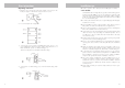
To replace the primary glass
1. Refer pages 13 and 14, steps 7 to 11, of the installation instructions.
Refit glass and replace in reverse order ensure the inside surface of the
glass is clean and free from finger marks.
To replace the outer glass
1. Remove the top two glass retaining posts using a 4mm allan key. Sup-
port the bottom of the glass and remove the two lower glass retaining
posts. Refit glass in reverse order ensuring the inside surface of the glass
is clean and free of finger marks.
Note: ensure the inside surface of the glass is clean and free from finger
marks.
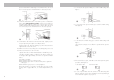
To replace the gas control
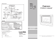
1. Remove the lower front cover by unscrewing two M5 screws through
the air intake slot. Refer page 13, figure 16, of the installation instruc-
tions.
2. The blue module (ignition device) needs to be removed to allow re-
moval of the gas control. Remove LH screw from front lower section of
ignition device. Remove screw from front of rectifier lead located below
domed cap on gas control.
3. Unplug polarise plug (wires feeding to module and gas control) and
remove spark/sense electrode connections, earth connection from mod-
ule and earth connection form gas control. Remove the module from the
gas control.
4. Disconnect the gas inlet (1/2” compression nut) connection at entry to
gas control and the 16mm nut at the outlet of the gas control.
5. Remove the three M3 screws from the cradle retaining the gas control.
Remove gas control.
6. Replace gas control and ignition device in reverse order and check for
gas tightness.
Note: check the gas pressure on high and low burner settings. Refer ‘gas
control’, pages 17 and 18.
To replace the ignition (module) device
1. Refer ‘to replace the gas control’ and perform steps 1 to 3, but do not
remove the earth connection from the gas control.
2. Remove RH screw from front lower section of ignition device.
3. Unplug wire connector from ignition device.
4. Replace ignition device in reverse order.
To replace the room circulation fan
1. Remove the lower front cover by unscrewing two M5 screws through
Service Instructions - (Do not modify this appliance)