Sharing a lifetime of cosy moments Inbuilt Heater Instruction Manual Please read this manual before installing and using this heater.
Contents Page Warranty 3 Safety Warnings 5 OperatiON 6 Optional Accessories 7 inbuilt: Fitzroy specifications 8 inbuilt: Canterbury specifications 9 Fitzroy & Canterbury Inbuilt Installation Instructions 10 – 11 Fitzroy & Canterbury Inbuilt Fluing options 12 Fitzroy Inbuilt Fascia Removal 13 Canterbury Inbuilt Fascia Removal 13 Electrical Connection & Sealing the Fascia 14 INSTALLING THE FLUE SPIGOT 14 Log Installation & GAS CONNECTION 15 SETTING THE GAS PRESSURE 16 Service Ins
warranty This Warranty against defects for your newly purchased Cannon product is proudly prepared by Sampford IXL Pty Ltd of 421 Smith Street, Fitzroy, VIC 3065, phone 1300 727 421. 1. Sampford IXL products come with guarantees that do not exclude the following consumer entitlements under the Australian Consumer Law: a. replacement or refund for a major failure and compensation for any other reasonably foreseeable loss or damage; and b.
11. Sampford IXL and its Authorised Service Dealers reserve the right to seek reimbursement of any costs incurred by them should your Cannon product be found to be in good working order. Privacy The privacy of your personal information has always been important to us. To learn more about how we collect, keep and use your personal information, please obtain a copy of our privacy statement by visiting our website at www.sampfordixl.com.au or by contacting us via email on info@sampfordixl.com.
Safety Warnings Please read this manual before installing and using the heater. Safety Warnings 1. What to do if you smell gas (a) Turn OFF the main gas supply (b) Extinguish any open flame (c) Open windows (d) Do not touch electrical switches (e) Do not use your telephone (f) Call your gas supplier immediately from a neighbour’s phone 2. Improper installation, adjustment, alteration, service or maintenance can cause injury or property damage.
OperatiON Operating Instructions Plug the power cord into the wall socket and turn on the power to the heater (FIG 1). Alternatively, switch on the isolation switch and circuit breaker at the main switchboard if the heater has fixed wiring. Refrain from using an extension cord. User controls FIG 2.
Optional Accessories Versatility and flexibility are key components of our installation options. If installed into a shallow recess or an existing fireplace, elegant spacers will eliminate any size discrepancies. To enhance your Cannon’s appearance add a decorative 3 or 4 sided surround. For added convenience the heater can now be connected to a home automation system, such as C-bus. This allows the heater to be turned on or off remotely (normal heat setting only).
inbuilt: Fitzroy specifications Cannon Fitzroy Inbuilt Gas type atural or Propane gas, N as indicated on data label Gas consumption 26.0 MJ/hr Energy output 5.98 kW / 21.45 MJ/hr Energy star rating 4.05 stars Heater type Gas space heater approved to AS 4553:2008 Operating pressure Natural gas 0.75 kPa (high) /0.40 kPa (low) Propane gas 2.65 kPa (high) / 1.1 kPa (low) Gas regulator Integral part of controller Min. inlet pressure .13 kPa (NG) 1 2.
inbuilt: Canterbury specifications Cannon Canterbury Inbuilt Gas type Natural or Propane gas, as indicated on data label Gas consumption 26 MJ/hr input Energy output 5.98 kW / 21.45 MJ/hr Energy star rating 4.05 stars Heater type Gas space heater approved to AS4553:2008 Operating pressure Natural gas: 0.75 kPa (high) /0.40 kPa (low) Propane gas 2.65 kPa (high) / 1.1 kPa (low) Gas regulator Integral part of controller Min. inlet pressure 1.13 kPa (NG) 2.
Fitzroy & Canterbury Inbuilt Installation Instructions Overview 1. This appliance MUST be installed by an authorised service person only. 2. This appliance shall be installed in accordance with the manufacturer’s installation instructions, local gas fitting regulations, municipal building codes, electrical wiring regulations, and AS5601 the Australian Standard for gas installations. 3. Open top of carton and remove accessories (logs). Lift carton up and remove.
Fitzroy & Canterbury Inbuilt Installation Instructions Ceiling 1000 mm min clearance Mantle 300 mm min clearance 385 mm 228 mm 100 mm Rear wall of fireplace 25 mm min 522 mm 900 mm min clearance 700 - 780 mm 690 mm 50 mm 690 mm 100 mm ** ** Ensure controls are visible FIG 5 FITZIB-SMENB/FITZIB-SMEXB/FITZIB-SMEXP Ceiling 1000 mm min clearance Mantle 300 mm min clearance 338 mm 180 mm 100 mm Rear wall of fireplace 25 mm min 522 mm 900 mm min clearance 700 - 790 mm 690 mm 50 mm 690 mm 100 m
Fitzroy & Canterbury Inbuilt FluEing Flue installation 500mm between top of cowl and nearest part of roof. (Also refer to AS 5601) Please note: Flueing of heater MUST be carried out by an authorised person. Refer to Australian Standard Gas Installations AS 5601. Flue cowl approved to AG604 Flue clamp Roof cladding Flashing Installing a flue on the shorter wall may subject it to down draughts or reverse air flows through the heater which can be difficult to find a solution to.
Fitzroy Inbuilt Fascia Removal 1. Remove the wire mesh grille by gently lifting it upwards and then outwards. Similarly remove a fitted glass kit by also gently lifting it upwards and then outwards. 2. Remove 4 M5 screws fixing the fascia assembly to the heater body. Bring the bottom of the fascia towards you gently to partly disengage it from the body of the heater. After it has been disengaged gently lift it up vertically to completely disengage it from the body of the heater. Refer FIG 8 & FIG 9.
Electrical Connection Electrical Connection This appliance is designed to operate on 240V AC power supply. Failure to operate unit at correct supply voltage may create unsafe conditions. All fixed wiring must be installed by a suitably qualified person and comply to the appropriate electrical wiring rules. Grommet The heater is supplied with a flexible power cord with a plug fitted. A 10 Amp switch socket must be located within 1.5m of the heater.
Log Installation 1. The burner is contained within the burner chamber. Refer FIG 17. 2. Carefully unpack the log set. Logs are numbered as follows: #1 - Left front log #2 - Left back log #3 - Right front log #4 - Right back log Burner in base of burner chamber FIG 17 Position the four individually numbered logs in the following order on the burner bed as shown in FIG 18-21. The locating pins on burner bed must engage with corresponding holes in the individual logs.
SETTING THE GAS PRESSURE 1. Gas valve layout is as indicated in FIG 25. Pressures for ‘Burner high flame’ and ‘Burner low flame’ are factory set, however if pressures need to be checked or adjusted follow the procedures described below. To check outlet pressure at burner ‘high flame’ and ‘low flame’ positions remove the plastic cap from the regulatior adjustment location as indicated in FIG 26. 2. The pressure point is closed with a captive screw.
Service Instructions (Do not modify this appliance) General chamber underside. Lower fan from male thread. 1. Service work MUST be carried out by an authorised service person only. 4. Disconnect the silicone tubes from the fan pressure switch. Remove fan from fan chamber. 2. Unplug from wall socket or turn off power at isolation switch if heater is hard wired. 5. Remove the venturi and bracket from the fan removed from the heater. Insert and secure the venturi and bracket on replacement fan.
Service Instructions (Do not modify this appliance) To Replace The Electronic Controller 1. Remove the front fascia. Refer to page 13 of the installation booklet. 2. Disconnect the plugs on box. 3. Remove the screw retaining the bracket. 4. Replace the electronic controller. 5. Check and re-set gas pressures. To Replace The Burner And Spark/Sense Electrodes 1. Remove the logs from the burner chamber. Refer page 15. 2. Remove the burner chamber front inspection panel, 4 screws. 3.
Wiring Diagram SWITCH COILS ON/OFF LOW BRN / LOW FAN MED BRN / MED FAN HIGH BRN / HIGH FAN SPARK ELECTRODE 3 WAY FLAME SENSOR SHEATHED HIGH TEMP DATA CABLE MODULATING VALVE F3691 EARTH BLUE RED BLACK MOD1 WHITE MOD2 RED NC H M L CONTROL MODULE F3828 A EARTH BLUE NO IGNITION MODULE F3833 240 V MAINS PLUG RED N BLUE N RED C 1 WAY PRESSURE SWITCH F3327 ROOM AIR FAN PURPLE 4 WAY C GREY BROWN 1.
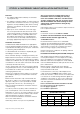
Troubleshooting To check the operation of the heater’s electrical system you will require a digital multimeter with the functions to measure ac/dc voltage, continuity, resistance and micro-amps. It is critical that the appliance is earthed and that the active and neutral are not reversed. Cannon Fitzroy and Canterbury Inbuilt There is a green and red LED on the ignition controller. These LEDs act as diagnostic aids when the heater safety systems produce a safe shutdown condition.
Troubleshooting Fault Codes Continued Long Short Morse Code Meaning 3 ———• Check the fan for dust build up and lint. Check that the room air fan is spinning. Check that the pressure tubes are connected correctly and not pinched or kinked. The black tube should run from the black side of the pressure switch Room fan (circulation to the bottom tapping on the fan venturi. The clear tube fan) pressure signal has should go from the light side of the pressure switch and to been interrupted.
Notes 22 | Cannon Canterbury Freestanding
Notes Cannon Canterbury Freestanding | 23
COPY RATING LABEL HERE Don’t Risk Your Appliance Warranty Only a licensed person will give you a compliance certificate, showing that the work complies with all the relevant standards. And only a licensed person will have insurance protecting their workmanship for 6 years. So make sure you use a licensed person to install this appliance and ask for your compliance certificate to ensure the manufacturers appliance warranty will be honoured.