
User Manual

2240 Fiber Optic Modem
17
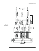
The heart of the 2240 transmitter is a ten-channel multiplexer. This multiplexer takes
the clock, data and control lead inputs from the interface, multiplexes them, then adds
framing and supervisory information. This composite data is then converted into a
Manchester-coded signal which drives the modulator of the optical transmitter.
The function of the multiplexer is highly dependent on the operating mode of the modem
(refer to Section 3). Supervisory information is related to frame synchronization and
loopback status.
1.4.4 Receive Section
An optical receiver circuit converts the incoming signal to a biphase logic signal. It is
then de-multiplexed into all necessary interface signals.
The receiver first extracts the clock and data information from the Manchester-coded
optical signal. After frame-bit lock is established, the de-multiplexer separates out the
clock, data and control lead signals, as well as the supervisory information. The
supervisory states are mainly routed to control status indicators, while the remaining
signals are routed to the interface circuits. The operation of the receiver is somewhat
dependent on the 2240 operating mode, but much less dependent than the transmitter.
1.4.5 Expanded Interface Control Channels
The 400 series of 2200 Series Fiber Optic Modem Interfaces can support additional
Control Leads up to a maximum of four. There are three channels dedicated to use for
Control. Refer to descriptions of these interfaces in Section 4, "Data Interfaces." The
fourth is the Aux Channel 1 input and output which is available on the expanded
interface connector.
1.4.6 Expanded Interface Auxiliary Channels
The 2240 has five Auxiliary Channels. One of these channels is available on the
expanded interface connector and the other four on the Auxiliary Interface Connector
(see Figure 3-4). The MC1 and MC2 interfaces make use of all eight control and
auxiliary channels (refer to Section 4).