
User Manual


2240 Fiber Optic Modem
55
4.5 CCITT V.35 (ISO 2593-1993) Model 436
This interface complies with CCITT Standard V.35 and ISO 2593-1993. Electrical
characteristics comply with V.35 for clock and data signals and RS-232 levels for
control signals.
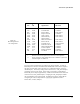
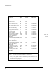
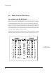
This interface uses the physical connector type and pinouts specified in ISO 2593-1993
(refer to Table 4-E). The V.35 interface uses a 34 pin female Winchester connector for
the physical connection.
Note that the table lists the function name shown in ISO 2593 and an aka where
applicable. The rest of this section refers to the ISO 2593 function name and aka
interchangeably. For example, the aka Serial Clock Transmit (SCT) is the same as
ISO 2593 Transmitter Signal Element Timing.
The TXD, RXD, SCT, SCR and SCTE pins carry the primary data and clock signals
(conforming to the V.35 standard). In addition, an extra clock signal input is provided
to make the 2240 / -436 combination more "DTE-like" in tail circuit applications at the
clock source end (refer to Section 2.2.6). The remainder of the pins are either ground
references or control signals. Transmit Data (TXD) and Receive Data (RXD) are the
data input and output signals for the modem, respectively.
Serial clock Transmit (SCT) is the modem’s transmit clock reference output that is
used for the internal and slave clock modes. Serial Clock Receive (SCR) is the clock
signal for the receive data unless the 2240's main PCBA W26 (XTCLK) jumper is ON,
in which case the Extra Clock input signal is used to shift receive data out from the
2240 (refer to Section 2.2.6). Serial Clock Transmit External (SCTE) is the transmit
clock signal used in either of the External clock modes or when the main board’s
internal CLK / EXT switch is set to EXT (refer to Section 3.7).