
User Manual

2240 Fiber Optic Modem
73
This interface performs jitter attenuation of the transmit line input signal. It is also
designed to propagate an all "1's" AMI stream if the end-to-end line is interrupted at
any point.
When using any of the Transparent Bipolar Interfaces, the 2240 modem rate and
mode front panel DIP switches should be set as follows: 1-4 = closed, 5-7 = open
(Rate 0, Mode 7). In addition, the first two positions of the internal DIP switch S1
must be:
CD / DCD = OFF and CD / SYNC = ON. Refer to Section 2.2.2.1.
If the interface signal is lost, Loss of Signal (LOS), the all "1's" Alarm Indication
Signal (AIS) is sent to the other end.
Factory Setting = Both jumpers are OFF
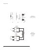
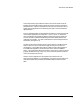
These interfaces allow full inter-operation with any of the synchronous data inter-
faces when the customer's T1/E1 is AMI-coded (see Figure 4-3). This interface will
not inter-operate with synchronous data interfaces if the T1 / E1 is B8ZS or HDB3.
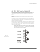
Two jumper straps are provided for setting the line termination impedance to either
100 ohm for T1 or 120 ohm for E1 applications. These straps are located near the
middle of the interface board and are provided only for the 4B1 and 4B2 versions.
For the 4B3 version (BNC connectors) the termination impedance is fixed at
75ohms.
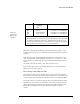
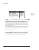
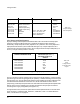
Table 4-N.
Transparent
Bipolar Line
Interfaces
Model # Interface Speed
Connector
Type
4B1 DA-15 1.544 Mhz T1 or 2.048 Mhz E1
4B2 Terminal Block 1.544 Mhz T1 or 2.048 Mhz E1
4B3 BNC (75 ohm) 1.544 Mhz T1 or 2.048 Mhz E1
These interfaces are fully transparent to line codes such as B8ZS or HDB3.
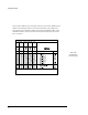
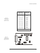
Three DIP switches (3, 4 and 5) are provided for selecting various line build
out settings as indicated in Table 4-M. Standard factory settings are T1 at
0-133 feet for all three models. Two DIP switches (1 and 2) are provided to
select CCITT speed (2.048 Mhz) or T1 speed (1.544 Mhz).