
User Manual

2240 Fiber Optic Modem
95
5. Troubleshooting
5.1 Diagnostic Procedures
The following procedures are intended for use in the event of a system failure, not
during the initial installation of a 2240 optical link. For initial installation checkout,
refer to Section 1.7 of this manual. Also, refer to Section 6 for detailed diagnostics.
5.2 Local and Remote Loopback
5.2.1 Loopback Tests
All 2240s have built-in Local and Remote Loopback. These tests can be used to
verify the basic operation of a 2240 system.
The test modes can be activated by setting the Loopback switch on the front panel or
by turning on the Local Loopback or Remote Loopback control leads in the electrical
interface (supported interfaces only). See Section 4 for more information.
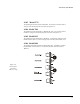
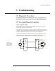
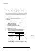
Whenever either modem has a Loopback selected, the Loop On indicators on both
modems will be on and the DSR signal on the interface may be negated (check
strapping of interface). Figure 5-1 shows a local loopback configuration.
HOST
TERMINAL
HOST
TERMINAL
USER
TERMINAL
TX
RX
RX
TX
LOOP
LED
ON
LOCAL
LOOP
LOOP
LOCAL
SYNC
SYNC
LOOP
OFF
LOOP
LED
ON
FIBER OPTIC LINK
Figure 5-1.
Local Loopback
from User-End
of Fiber Link