
Manual


Caution:
To avoid damaging the fiber end-surface or connector, use extreme care when
installing or removing cables.
8. Plug in the optical cables:
If you have a simplex optical connector, use a single strand, single mode fiber cable between
a pair of 2340 modems, one at 1310 nm wavelength and the other at 1550 nm wavelength.
If you have a duplex connector, use Tx to Rx, and Rx to Tx orientation.
9. Label each cable and connector with a signal name and direction.
10. For cable connections to other modules in the chassis, see the appropriate user manual for details.
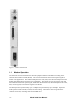
2.2 Power Up and Front Panel Functions
During the initial power-up sequence, all LEDs light amber. When start-up is complete, the setup and
installation are correct, and data is transmitting normally across the link, the STA LED lights green
and the CFG, CLS, and TST LEDs are off. During normal operation, the LED colors change
according to system and port conditions. The STA, CFG, and TST LEDs show the module condition.
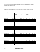
The CLS LED shows the optical signal conditions. Table 1 shows the LED states for various
conditions.
Table 1.
2340 LED Functions
LED Status Description
STA Off No power
Green Normal operation
Amber Inactive (redundant modem)
Red Failed system self-test
CFG Off Normal operation
Red Software mismatch between local and remote modems, improperly
connected fiber optic cable, or setup mismatch between local and
remote modems
CLS Off Normal operation
Red Local loss of optical sync
Red blinking Remote loss of optical sync
TST Off Normal operation
Amber Local loopback (optical or electrical)
Amber blinking Remote loopback (optical or electrical)
Model 2340 User Manual
2-2