
Instruction Manual


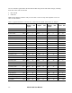
Table Of Contents
- General Safety Considerations
- Chapter 1 Chapter 1Overview
- Chapter 2 Chapter 2Installation and Setup
- Chapter 3 Chapter 3Electrical Data Interfaces
- 3.1 L130: Configurable EIA-232/423/530/P53/449/V35
- 3.2 P53 Interface for the L130
- 3.3 L131: EIA-422, DC-37 With Control Signals
- 3.4 L132: EIA-422, TwinAx
- 3.5 L133: TTL, BNC
- 3.6 L134, L135, L136, L137: T1 and E1
- 3.7 L138: EIA-422, DC-37 Without Control Signals
- 3.8 L139: T88
- 3.9 Operating Modes and Transmit/Receive Timing
- Chapter 4 Chapter 4Software Management
- 4.1 VT100 Terminal Emulation
- 4.2 PC Configuration for Terminal Operation
- 4.3 Management User Interface
- 4.4 2370 Main Menu
- 4.5 System Configuration
- 4.6 Hardware Configuration
- 4.7 Functional Configuration
- 4.8 Trap Configuration
- 4.9 Alarm Output Configuration
- 4.10 SNMP Configuration
- 4.11 Host Table
- 4.12 Diagnostics
- 4.13 Interface Status
- 4.14 Link Error Counters
- 4.15 System Alarms
- 4.16 Utilities
- 4.17 PING
- 4.18 Software Upgrade
- Chapter 5 Chapter 5Troubleshooting
- Chapter 6 Chapter 6Specifications

The V.35 inte
rface signals follow the EIA-423 and EIA-232 protocols with minor changes, including
these three end-to-end control leads:
RTS to DCD
DTR to RI
DSR indicates that the modem is ready to receive data. TM is On only when loopback is active on
either or both modems.
Table 2. Signals and Pinouts: EIA-423/232, -530 Protocols and EIA-449/42 and V.35 Adapters
Signal Name Path EIA-
423/232
Signal
DB-25
Pin
EIA-530
Signal
DB-25
Pin
EIA-
449/422
Signal
DC-37
Pin
CCITT
Circuit
V.35
Pin
Frame Ground FG 1 FG 1 SHLD 1 101 A
Transmit Data In TD 2 TDA 2 SD 4 103 P
Receive Data Out RD 3 RDA 3 RD 6 104 R
Request to Send In RTS 4 RTSA 4 RS 7 105 C
Clear to Send Out CTS 5 CTSA 5 CS 9 106 D
Data Set Ready Out DSR 6 DSRA/B 6/22 DM 11 107 E
Signal Ground SG 7 SG 7 SG 19 102 B
Data Carrier Detect Out DCD 8 DCDA 8 RR 13 109 F
Secondary RC Out RXCB 9 RT 26 115 X
Secondary DCD Out DCDB 10 RR 31
Secondary TT In SCTEB 11 TT 35 113 W
Secondary DCD Out SDCD 12 TXCB 12 ST 23 114 Y
Secondary CTS Out SCTS 13 CTSB 13 CS 27
Secondary TD In STD 14 TDB 14 SD 22 103 S
Transmit Clock Out SCT 15 TXCA 15 ST 5 114 AA
Secondary RD Out SRD 16 RDB 16 RD 24 104 T
Receive Clock Out SCR 17 RXCA 17 RT 8 115 V
Local Loopback In LL 18 LLA 18 LL 10 141 L
Secondary RTS In SRTS 19 RTSB 19 RS 25
Data Terminal Ready In DTR 20 DTRA/B 23/20 TR 12 108 H
Remote Loopback In RL 21 RLA 21 RL 14 140 N
Ring Indicator Out RI 22 DM 29 125 J
Data Signal Rate Selector In DSRS 23 TR 30
Terminal Timing In SCTE 24 SCTEA 24 TT 17 113 U
Test Mode Out TMA 25 TMA 25 TM 18 142 NN
Model 2370 User Manual
3-2