LAN Chassis Canoga Perkins Model 9101 LAN Chassis
NOTICE Canoga Perkins reserves the right to change or update the contents of this manual and to change the specifications of its products at any time without prior notification. Every effort has been made to keep the information in this document current and accurate as of the date of publication or revision. However, no guarantee is given or implied that the document is error free or that it is accurate with regard to any specification.
Canoga Perkins Model 9101 LAN Chassis supports 10Mbps, 100Mbps Media Converters, and WA-2 Passive WDM
9101 LAN Chassis Canoga Perkins Table of Contents Chapter 1 - Overview ........................................... 7 1.1 9101 LAN Chassis Application .................................... 8 1.2 Packing List .................................................................. 8 Chapter 2 - Chassis Installation ........................... 9 2.1 9101-0 LAN Chassis ..................................................... 9 2.2 9101-1, 2, 3 or 4, LAN Chassis ...................................
Canoga Perkins List of Figures 1-1 1-2 9101 LAN Chassis (Front View) ............................................ 7 9101 LAN Chassis Application ................................................ 8 2-1 2-2 2-3 9101-0 LAN Chassis ............................................................. 9 DC Power Connector Configuration ...................................... 10 Power Supply Cables in 9101-1, 2, 3 or 4 LAN Chassis ......
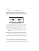
9101 LAN Chassis Canoga Perkins Chapter 1 - Overview The 9101 LAN Chassis is designed to house any mix of up to twelve 8814s, 8829s, 9119s, and WA-2s (see Figure 1-1).
Canoga Perkins 9101 LAN Chassis 1.1 9101 LAN Chassis Application Figure 1-2 shows a typical application utilizing the elements of the 8800-series 10Mbps and 9100-series Fast Ethernet devices. Figure 1-2 9101 LAN Chassis Application 1.2 Packing List If the 9101 LAN Chassis is ordered with power supplies, the power supplies will be inserted into the unit and 19-inch chassis ears will be attached, as will the front panel.
101 LAN Chassis Canoga Perkins Chapter 2 - Chassis Installation 2.1 9101-0 LAN Chassis The Model 9101-0 LAN Chassis is non-powered and designed to support the 8814 Fiber Optic Transceivers and the WA-2, 2-Port passive WDM module. The transceivers receive their power from the attached DTE device via the AUI cable. Therefore, the setup and installation of the LAN chassis is very straight forward. Ensure you have the necessary equipment available for the setup requirements. Setup Requirements: 1.
Canoga Perkins 9101 LAN Chassis 2.2 9101-1, 2, 3 or 4, LAN Chassis The 9101-1, 2 ,3 or 4, LAN Chassis configuration accommodates single or redundant hot-swappable, load sharing 120/240VAC or 48VDC power supplies. The 48VDC power versions can be configured as +48VDC or -48VDC: connect the earth ground jumper from the center terminal to either -V or +V terminals respectively, on the DC power input connector (see Figure 2-2). A power ON switch is provided for both AC and DC versions.
9101 LAN Chassis Canoga Perkins Figure 2-3 Power Supply Cables in 9101-1, 2, 3 or 4, LAN Chassis NOTE: To facilitate installations of both plastic and metal case devices, the 9101 LAN Chassis has notations on the front to indicate the appropriate slot for metal (M) and plastic (P) devices. The 48 plastic guides are factory-installed for use with both the 9119 Media Converter metal case module and the plastic case 8829 Media Converter.
Canoga Perkins 9101 LAN Chassis This page is intentionally blank 12
9101 LAN Chassis Canoga Perkins Chapter 3 - Module Installation 3.1 8814 Fiber Optic Transceiver Once the 9101 LAN Chassis is installed, the 8814 Fiber Optic Transceivers may be cabled and inserted into the chassis. Step 1 First, note that the orientation of the 8814 Fiber Optic Transceiver is intended such that the LED indicators on its front panel face out, with cable connections made from the rear.
Canoga Perkins 9101 LAN Chassis Step 3 Since the 8814 case is plastic, ensure that card guides have been installed at the top and bottom of the rack in the positions marked "P" at each location where an transceiver is to be installed. Insert the cabled transceiver vertically into the chassis, aligning the guides on the top and bottom of the transceiver case with the "P" card guides on the 9101 LAN Chassis (see Figure 3-2). The AUI cable should be oriented to the top.
9101 LAN Chassis Canoga Perkins 3.2 Media Converters (Models 8829, 9119) Once the 9101-1, 2, 3 or 4, LAN Chassis is installed, the Media Converters may be cabled and inserted into the chassis. Fiber Optic Transceivers and Media Converters can be co-located in this same LAN chassis, although only the Media Converters are connected to the power distribution board.
Canoga Perkins Step 2 9101 LAN Chassis Attach the appropriate fiber optic cables to the media converter. The connections should be made with the unit out of the LAN chassis (see Figure 3-4). Figure 3-4 Fiber Optic Cable Connections on Media Converter Step 3 Since the 9101 card guides are factory-configured for 9119 metal cases, ensure that card guides have been installed at the top and bottom of the LAN chassis in positions marked "P" at each location where an 8829 is to be installed.
9101 LAN Chassis Canoga Perkins Step 4 Attach the 10BASE-T/100BASE-TX UTP cable by first bringing it between the lower rack and chassis bottom, and extending it out the front. Then insert the cable connector into the 8-pin modular jack on the front panel of the 8829/9119 Media Converter (see Figure 3-6). NOTE: Refer to the 8829 User Manual for proper setting of the "NORM/X" switch, or the 9119 User Manual for proper selection of NORM or X connector.
Canoga Perkins 9101 LAN Chassis 3.3 Connection to Alarm Contacts The alarm contacts for the 9101 LAN Chassis are located in the middle of the upper portion of the chassis and are shown in Figure 3-7. A set of alarm contacts is associated with each power supply. Alarm Contacts Connection Chassis Ground Connection Figure 3-7 9101 LAN Chassis (Rear View) NOTE: The alarm contacts located on the rear of the 9101 LAN Chassis are relay contacts that either open or close a circuit.
9101 LAN Chassis Canoga Perkins The chassis alarm contacts are illustrated in Figure 3-8. The interpretation of the alarms are as follows: Norm Open Open during normal operation / closed during a power fault condition. Common The common pin between alarm contacts. Norm Clsd Closed during normal operation / open during a power fault condition. Figure 3-8 9101 LAN Chassis Alarm Contacts 3.
Canoga Perkins 9101 LAN Chassis If a +48 VDC supply is indicated, the strap is connected from the Chassis Ground to the -VDC terminal. Then the positive (+) lead from the source DC supply and the negative (-) or Common lead from the source DC supply are also connected to like terminals on the 9101 power entry barrier strip as above. If the connections are reversed with opposites connected, damage may result to both the source DC, and DC converter module in the 9101 LAN Chassis.
9101 LAN Chassis Canoga Perkins Chapter 4 - Troubleshooting 4.1 Mechanical The 9101 LAN Chassis is designed in conformance with ANSI/EIA Standard RS 310-D for 19-inch relay racks and installs easily in any compliant relay rack. Should you experience difficulty installing the unit, verify that the relay rack meets the above standard. 4.
Canoga Perkins 9101 LAN Chassis Problem: The power LED on an media converter does not turn on. Solution: Check that at least one 9101 LAN Chassis power supply indicator is illuminated to confirm that the supply is operational.
9101 LAN Chassis Canoga Perkins If during your trouble shooting, you have determined that a P/S is defective, you can replace it without disrupting the normal operation of the chassis and media converters, provided your 9101 is equipped with a redundant P/S. The following steps explain how to replace a faulty unit without having to power down the chassis and disrupt service.
Canoga Perkins 9101 LAN Chassis Step 2: Move so that you have access to the back side of your 9101 Chassis. If the P/S you are replacing is DC, ensure that the Power Switch is in the OFF position. (AC supplies do not have a Power Switch). Disconnect the power cord. Remove the nut that fastens the P/S to the chassis and put it in a location where it will not get lost.
9101 LAN Chassis Canoga Perkins Figure 4-3 Replace Power Supply - Step 3 Step 4: After you have removed the faulty P/S, set the replacement on the chassis where the defective one was removed. Note the slot on the back end of the P/S. This is the guide slot that will fit around the raised tab that makes up the back of the P/S guide. The P/S guide is located along the side of the chassis on which the power supply will rest. Reference Figure 4-4.
Canoga Perkins 9101 LAN Chassis Step 5: Reinsertion of the power supply cable will be more difficult than it's removal. Look inside the chassis prior to insertion and calculate the proper orientation of the plug, then reinsert it. Realign the P/S in it's guide. If you experience resistance, adjust the supply slightly until it can be easily placed within it's guides. Once the P/S is in place, secure it to the chassis.
9101 LAN Chassis Canoga Perkins Chapter 5 - Specifications 5.1 9101-0 LAN Chassis Dimensions: 19" W x 15" D x 8.75" H Weight: 7 lbs (chassis unloaded) Temperature: 0 to 40°C Humidity: 0 to 95% (non-condensing) 5.2 9101-1, 2, 3 or 4 LAN Chassis 5.2.1 Power Requirement: Power Supply: Single or Dual, AC or DC Power Input: AC power supply (85-132/170-264VAC, 47-63Hz at 1.2/0.75A) +/-48VDC (+/- 36-76VDC) at 3.
Canoga Perkins 9101 LAN Chassis 5.2.2 Physical / Environmental: Dimensions: 19" W x 15" D x 8.75" H Weight: Rack Chassis: Power Supply: 7 lbs 2 lbs each Temperature: 0 to 40°C Humidity: 0 to 95% (non-condensing) 5.2.3 Certification/Compliance Conforms to Bellcore 'Network Equipment Building Systems' (NEBS) Level 3 Standards.
9101 LAN Chassis Canoga Perkins Appendix A Warranty Limited Lifetime Warranty Effective July 1, 2005 and After, Canoga Perkins warrants that, at the time of sale, and, for its lifetime, with certain exceptions noted below, every Canoga Perkins’ labeled product purchased will be free from defects in material and workmanship for its lifetime, if properly installed and used in conformity to Canoga Perkins' published specifications. This warranty covers the original user only and is not transferable.
Canoga Perkins Optional Service Programs Canoga Perkins offers several optional Service Programs. Please call Canoga Perkins Sales Department (818-718-6300) or see our web site (www.canoga.com) for details.
9101 LAN Chassis Canoga Perkins Return Policy Customer must obtain an RMA (Return Material Authorization) number from the Canoga Perkins Customer Service Department before returning a product for service or repair. Canoga Perkins' technical support department can be reached through any of the following means: Telephone: 818-718-6300 Fax: 818-718-6312 E-Mail: fiber@canoga.