PUB.
COPYRIGHT WARNING: Unauthorized recording of copyrighted materials may infringe on the rights of copyright owners and be contrary to copyright laws. 2 Trademark Acknowledgements • SD, SDHC and SDXC Logos are trademarks of SD-3C, LLC. • Canon is an authorized licensee of the CFast 2.0™ trademark, which may be registered in various jurisdictions. • Microsoft and Windows are trademarks or registered trademarks of Microsoft Corporation in the United States and/or other countries.
Highlights of the Camera The Canon EOS C200 / EOS C200B Digital Cinema Camera is the latest camera in the highly-respected Cinema EOS line. Cinema EOS cameras are increasingly relied upon by industry professionals due to their state-of-the-art technology and the cameras’ high quality. The C200 / C200B continues that tradition by offering many features that will help you articulate your creative vision.
Even while focusing manually, the Dual Pixel Focus Guide function (A 82) serves as a visual, intuitive guide that you can use to check if the image is in focus and the required adjustment, if it is not. This can be very helpful to ensure you always get amazingly sharp 4K video. 4 Remote operation You can attach the optional RC-V100 Remote Controller to the camera to control it from a distance. The remote controller lets you control a wide range of camera settings (A 118).
Table of Contents 5 1.
White Balance 77 Custom White Balance 77 Color Temperature/Preset White Balance 78 Auto White Balance (AWB) 79 Adjusting the Focus 80 Manual Focus 81 One-Shot AF 84 AF-Boosted MF 84 Continuous AF 85 Changing the AF Frame Size and Position 86 Face Detection 87 Tracking a Specific Subject 88 Zooming 89 Onscreen Markers and Zebra Patterns 90 Displaying Onscreen Markers 90 Displaying Zebra Patterns 91 Setting the Time Code 92 Selecting the Time Code Mode 92 Selecting Drop or Non-Drop Frame 93 Putting the Time
6. External Connections 139 8.
1 Introduction 9 About this Manual Thank you for purchasing the Canon EOS C200 / EOS C200B*. Please read this manual carefully before you use the camera and retain it for future reference. Should the camera fail to operate correctly, refer to Troubleshooting (A 190). * Availability differs from area to area. Conventions Used in this Manual • IMPORTANT: Precautions related to the camera’s operation. • NOTES: Additional topics that complement the basic operating procedures. • A: Reference page number.
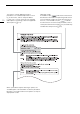
About this Manual 10 The arrow is used to abbreviate steps in procedures. For a detailed explanation on how to use the menus, refer to Using the Menus (A 33). For a concise summary of all available menu options and settings, refer to the appendix Menu Options (A 171). When a procedure requires selecting an option, the available options are listed within or after the procedure. Brackets [ ] are used to refer to menu options as they are displayed on screen.
Supplied Accessories Supplied Accessories The following accessories are supplied with the camera. Note that some accessories are supplied only with the C200. 11 LM-V1 LCD Monitor1 LA-V1 LCD Attachment Unit1 UN-5 Unit Cable1 HDU-2 Handle Unit1 Microphone Holder (incl. M4 fixation bolts (x 2)) GR-V1 Camera Grip1, 2 (incl. grip attachment ring) CA-A10 AC Adapter (incl. power cord) BP-A30 Battery Pack (incl.
Names of Parts Names of Parts 7 12 8 1 9 2 3 11 10 4 12 5 6 13 14 15 1 2 16 17 18 19 Tape measure hook and focal plane mark MAGN.
Names of Parts p15 11 1 12 13 14 15 2 3 16 4 5 6 8 9 7 10 17 18 19 1 2 3 4 5 6 7 8 9 INPUT 1 terminal (XLR) (A 98) INPUT 2 terminal (XLR) (A 98) SDI terminal (A 139, 141) × (headphone) terminal (A 104) USB terminal (A 108, 147) (Ethernet) terminal (A 156) DC IN terminal (A 26) (Ethernet) indicator (A 156) REMOTE terminal For connecting the optional RC-V100 Remote Controller or commercially available remote controllers.
Names of Parts 1 2 14 4 5 6 7 8 9 10 3 EF lens mount 1 2 3 4 5 Tally lamp (A 56) VIDEO terminal (A 28) PUSH AUTO IRIS (momentary automatic aperture) button (A 74)/ Assignable button Camera 10 (A 119) Built-in monaural microphone (A 103) EF lens mount index (A 37) 6 7 8 9 10 EF-S lens mount index (A 37) Lens release button (A 37) EF lens lock pin (A 37) EF lens contacts (A 37) ONE-SHOT AF (focus automatically once) button (A 84)/ Assignable button Camera 11 (A 119)
Names of Parts 13 k 15 14 1 2 3 15 l 4 4 5 5 6 7 8 9 6 7 8 9 16 17 18 16 17 18 10 11 12 1 2 3 4 5 Eye sensor (A 40) Viewfinder (A 40, 41) Dioptric adjustment lever (A 40) Tally lamp (A 56) FUNC (main functions) button (A 66)/ Assignable button Camera 8 (A 119) 6 Joystick (A 33) 7 CANCEL button (A 33) 8 MENU button (A 33, 119) 9 Cover for audio controls 10 AUDIO STATUS (display Audio status screen) button (A 185)/ Assignable button Camera 9 (A 119) 11 Audio level switches for CH1 (top) and CH2
Names of Parts 1 2 4 3 5 6 7 8 9 10 16 1 2 3 4 Tape measure hook Use the hook to accurately measure the distance from the focal plane. Accessory socket For mounting accessories with 1/4"-20 screws (6.9 mm (0.27 in.) deep). Strap mounts (A 44) Screw holes for 1/4"-20 mounting screws (7.5 mm (0.30 in.) deep) 5 Screw hole for 3/8"-16 mounting screws (10 mm (0.39 in.) deep) (A 42) 6 TB-1 Tripod Base 7 Tripod socket for tripods with 0.95 cm (3/8 in.) screws (5.5 mm (0.22 in.
Names of Parts LM-V1 LCD Monitor1 and LA-V1 LCD Attachment Unit1 1 Supplied accessory for the C200; optional accessory for the C200B.
Names of Parts GR-V1 Camera Grip1 k At the time of purchase, the camera grip is pre-attached to the camera. 18 4 1 2 5 6 7 3 8 9 10 1 2 3 4 5 1 Control dial (A 70, 72) REC (start/stop recording) button (A 56) Grip belt (A 44) Joystick (A 33)/SET button (A 33) FOCUS GUIDE button (A 82)/ Assignable button Grip 1 (A 119) 6 Rosette Compliant with ARRI rosettes.
Names of Parts HDU-2 Handle Unit1 1 2 1 3 4 5 19 6 1 2 3 4 1 2 Screw holes for 1/4"-20 screws (6 mm (0.24 in.) deep; 4 in total on the handle unit. Front accessory mount2 Includes a screw hole for 1/4"-20 screws (8.8 mm (0.35 in.) deep) Top accessory shoe Through-holes (∅ 8.8 mm (0.35 in.)) 7 5 6 7 Supplied accessory for the C200; optional accessory for the C200B. With socket for 0.
4K Workflow Overview 4K Workflow Overview The following illustrates the typical 4K workflow for this camera. 20 Operating modes: Recording Post-production HDMI OUT terminal Full-quality data External 4K recorder 4K recording (MP41) Full-quality data 4K RAW data Cinema RAW Development CFast card SD card 4K recording (RAW) 2K recording (MP4) Proxy data2 Proxy data2 Color grading EDL NLE software RAW plugin 1 2 The MP4 recording has a resolution of 3840x2160.
4K Workflow Overview Color Grading with the ACES Workflow Post-production RAW data CFast card MP4 data SDI terminal Cinema RAW Development OpenEXR (ACES 1.0) Input Transform Color grading ASCCDL Input Transform SD card ACESproxy Output Transform Inverse log ASC-CDL Output Transform On-set Color Grading ACESproxy: ACESproxy video data that is output from the SDI terminal when performing on-set color grading.
4K Workflow Overview 22
2 Preparations 23 Preparing the Power Supply You can power the camera using a battery pack or directly using the AC adapter. If you connect the AC adapter to the camera while a battery pack is attached, the camera will draw power from the power outlet. Using a Battery Pack You can power the camera using the supplied BP-A30 Battery Pack or the optional BP-A60 Battery Pack.
Preparing the Power Supply 24 Differentiating the Supplied Power Cords (for North America) The CA-A10 AC Adapter and CA-CP200B Compact Power Adapter each include a power cord. The plug for the CA-A10’s power cord has a socket with a straight side, while the plug for the CA-CP200B’s power cord has circular sockets. CA-A10 power cord plug CA-CP200B power cord plug IMPORTANT • Do not connect to the battery charger any product that is not expressly recommended for use with this camera.
Preparing the Power Supply Attaching the Battery Pack 1 Set the Q switch to OFF. 2 Insert the battery pack all the way into the compartment as shown in the illustration and press it gently toward the left until it clicks. Removing the Battery Pack 1 Set the Q switch to OFF. 2 Holding down the BATTERY RELEASE button, slide the battery pack toward the right and then pull it out.
Preparing the Power Supply Checking the Remaining Battery Charge 26 When the camera is turned on, you can check the approximate remaining battery usage time (in minutes) by looking at any recording/playback screen or the [Battery/Hour Meter] status screen (A 187). You can also check the approximate charge level on the battery pack itself. Press the CHECK button on the battery pack. An indicator will light for approximately 3 seconds and show the approximate remaining battery charge.
Preparing the Power Supply Connecting the CA-A10 AC Adapter 1 Set the Q switch to OFF. 2 Connect the AC adapter’s DC plug to the DC IN terminal on the camera. • Align the cable so the red dot on the plug is facing up. • To disconnect the AC adapter, pull back the metallic tip of the plug and then disconnect the cable from the terminal. 27 3 Connect the power cord to the AC adapter and plug it into a power outlet.
Preparing the Handle Unit and LCD Monitor Preparing the Handle Unit and LCD Monitor 28 By attaching the LA-V1 LCD Attachment Unit1 to the LM-V1 LCD Monitor1, you can attach the LCD monitor to the HDU-2 Handle Unit1 or directly to the camera body itself. For details on adjusting the LCD monitor, refer to Using the LCD Monitor (A 40) and Adjusting the LCD Screen or Viewfinder (A 41). 1 Supplied accessory for the C200; optional accessory for the C200B.
Preparing the Handle Unit and LCD Monitor 4 Rotate the LCD monitor mount 180° toward the handle unit. 5 Using the UN-5 Unit Cable2, connect the camera’s VIDEO terminal to the LCD monitor’s VIDEO terminal. 2 29 Supplied with the LM-V1. • Align the Í marks on the cables’ plugs and terminals. • Put the cable though the LCD attachment unit’s cable clamp. If necessary, adjust the position of the cable so that it does not get in the way of the lens.
Preparing the Handle Unit and LCD Monitor 30 5 Attach the LCD monitor. • Use the socket for 1/4"-20 screws on the bottom of the LCD monitor. • Use the hex wrench to secure it firmly with the hex socket head bolt. 6 Rotate LCD attachment unit pivot A 180° toward the SD card slots and then rotate pivot B 90° toward the lens. 7 Using a UN-5 Unit Cable2, connect the camera’s VIDEO terminal to the LCD monitor’s VIDEO terminal. 2 Supplied with the LM-V1. • Align the Í marks on the cables’ plugs and terminals.
Date, Time and Language Settings Date, Time and Language Settings Setting the Date and Time You will need to set the date and time on the camera before you can start using it. When the internal clock is not set, or if the settings were lost because the lithium button battery is depleted, the [Date/Time] screen will appear automatically with the time zone selected when you turn on the camera.
Date, Time and Language Settings Changing the Language 32 The camera’s default language is English. You can change it to German, Spanish, French, Italian, Polish, Portuguese, Russian, Simplified Chinese, Korean or Japanese. Please note that some settings and screens will be displayed in English, regardless of the language setting. Operating modes: 1 Press the MENU button. 2 Push the joystick up/down to select [B ! System Setup] and then press the joystick.
Using the Menus Using the Menus Many of the camera’s functions can be adjusted from the menu that opens after pressing the MENU button. In mode, you can also register frequently used menu settings in a customized submenu (My Menu) for easy access. For details about the available menu options and settings, refer to Menu Options (A 171).
Using the Menus 4 Push the joystick left/right to select the desired “page” number and then up/down to select the desired menu item. 5 Press the joystick. • Setting options will appear with a Ð mark next to the currently selected option. 34 6 Push the joystick up/down to select the desired setting option and then press the joystick. 7 Press the MENU button to close the menu.
Using the Menus Rearranging Menu Settings 1 Open the My Menu [Move] screen. > [¥ My Menu] * > [Edit] > [Move] * Each My Menu set appears on a different page. Select the page that corresponds to the desired set. 2 Push the joystick to select the setting you want to move and then press the joystick. • The ] icon will appear next to the setting you selected to move. 3 Push the joystick up/down to move the setting to the desired position and then press the joystick.
Preparing the Camera Preparing the Camera This section outlines the basic preparations for the camera such as attaching a lens and attaching the modular units to the camera: GR-V1 Camera Grip1, thumb rest, eye cup1, etc. 36 1 Supplied accessory for the C200; optional accessory for the C200B. Configuring the Modular Units Your camera is nothing if not versatile and you can choose the configuration that best fits your needs and shooting conditions.
Preparing the Camera • You can use the optional RD-1 Rod Clamp to use the camera with a commercially available viewfinder or other accessories with a ∅ 15 mm (0.59 in.) rod. RD-1 Rod Clamp (optional) Preparing the Lens As much as possible, attach and remove the lens quickly and in a clean environment free of dust. Refer also to the instruction manual of the lens used. IMPORTANT • When attaching/removing a lens, avoid direct sunlight or strong light sources. Also, be careful not to drop the camera or lens.
Preparing the Camera 38 NOTES • Turning on the image stabilization function of an EF lens may reduce the effective usage time of the battery pack. When image stabilization is not necessary, for example if the camera is fixed to a tripod, it is recommended to turn it off. • Depending on the lens used, you may experience one or more of the following limitations. - The lens model name may be shortened when displayed on the screen.
Preparing the Camera In-Camera Lens Correction Depending on the characteristics of the lens used, the corners of an image frame may be darker than the center due to light fall-off (peripheral illumination drop), or color shift/color fringing may be visible along high-contrast edges in the image (chromatic aberration). If the camera has correction data available for the EF lens used, it can apply this correction data to compensate as necessary. Operating modes: 1 Attach the lens you want to use.
Preparing the Camera Using the LCD Monitor You can rotate and position the LCD monitor in a number of ways to match your shooting style. 40 1 Rotate the LCD monitor mount 90° toward the lens. • Make sure LCD attachment unit alignment mark (on LCD attachment unit pivot A) and – (on the LCD monitor mount) are aligned. 2 Rotate LCD attachment unit pivot B 180° toward the CFast card slot.
Preparing the Camera IMPORTANT • Pointing the viewfinder lens at the sun or other strong light sources may cause damage to internal components. When you are not using the viewfinder, make sure to attach the viewfinder cap to the viewfinder. This will also protect the viewfinder from scratches and dirt. Attach the viewfinder cap by inserting it into the rubber rim of the viewfinder unit.
Preparing the Camera Setting the Screen to Black & White The viewfinder and LCD screen display in color by default but you can set them to black & white. Even when the screen is black & white, onscreen text and icons will still be displayed in color. 42 Operating modes: 1 Open the display selection menu for the viewfinder or LCD screen. > [¢ $ Monitoring Setup]1 > [B&W Image: VF Output] (k only) or [B&W Image: VIDEO Output] 1 l Appears on the previous page in the menu.
Preparing the Camera Removing and Attaching the GR-V1 Camera Grip The camera grip comes originally attached to the C200; it is an optional accessory for the C200B. You can remove it and replace it with the thumb rest should the minimal configuration be necessary. 43 Removing the Camera Grip 1 Set the Q switch to OFF. 2 Unscrew the camera grip’s lock screw and gently detach the camera grip. • The camera grip contains an internal connection cable so be sure not to pull it too forcefully.
Preparing the Camera Adjusting the Grip Belt 44 Adjust the grip belt so that you can reach the REC button on the camera grip with your index finger but still have a comfortable but secure grip. Attaching the Microphone Holder 1 Attach the microphone holder to the LCD attachment unit. • You can also attach the microphone holder to the camera directly. 2 Use a commercially available Phillips head (“crosshead”) screwdriver to secure it firmly with the supplied M4 bolts (length 20 mm (0.79 in.)).
Preparing the Camera Removing and Attaching the Terminal Covers You can remove the covers of the camera’s terminals to access them more easily. Removing the Terminal Covers Open the terminal cover and gently pull it straight out. Attaching the Terminal Covers Insert the connecting strip into the opening to attach the terminal cover. NOTES • If the connecting strip is difficult to grasp, use a pair of tweezers or similar tool.
Preparing the Camera Using the Optional EVF-V70 Electronic Viewfinder 46 You can attach the optional EVF-V70 OLED Electronic Viewfinder (1920x1080 pixels) to the camera instead of the LCD monitor and use the buttons and dials on the EVF-V70 to operate the camera. Attaching the EVF-V70 also requires attaching the handle unit1 and optional CL-V2 Clamp Base. The assistance functions that can be output to the LCD monitor through the VIDEO terminal will also be output to the EVF-V70.
Preparing Recording Media Preparing Recording Media The camera records clips1 on CFast or SD cards2 and photos on SD cards. The camera features two SD card slots. When you insert two SD cards in the camera, the camera can record 4K clips simultaneously on both cards, or it can switch automatically to recording on the other SD card when an SD card becomes full. Initialize recording media (A 50) when you use them with this camera for the first time.
Preparing Recording Media Inserting a CFast Card 1 Slide the CFast card slot cover switch in the direction of the arrow. 48 • The CFast card slot cover will open. 2 Insert the CFast card straight, with the label facing the SD card slots, all the way into the slot. 3 Close the CFast card slot cover. • Do not force the cover closed if the CFast card is not correctly inserted. CFast card access indicator CFast indicator CFast card status Red Accessing the CFast card.
Preparing Recording Media Inserting and Removing an SD Card You can insert an SD card into SD card slot A or slot B. If you have two SD cards, you can use both slots. 49 1 Open the SD card slot cover. 2 Insert the SD card, with the label facing the right side of the camera (the side with the air intake vent), all the way into the SD card slot until it clicks. • To remove the SD card, make sure the SD access indicator is off and then push the SD card once to release it.
Preparing Recording Media Initializing Recording Media The first time you use a recording media with this camera, initialize it first. You can also initialize a recording media to permanently delete all the data it contains. 50 When initializing an SD card, you can select quick initialization, which clears the file allocation table but does not physically erase the stored data, or complete initialization, which deletes all data completely. Operating modes: 1 Open the [Initialize Media] submenu.
Preparing Recording Media Switching Between the SD Card Slots The camera features two SD card slots, SD card slot A and SD card slot B. If both slots contain an SD card, you can switch between them as necessary. Operating modes: Press the SLOT SELECT button. • The access indicator of the selected SD card slot will illuminate in green. On the screen, the SD card selected is indicated with a Ð mark next to SD card icon.
Preparing Recording Media Checking the Remaining Recording Time on Recording Media 52 In mode, the display on the upper left of the screen shows the recording media icons and the remaining recording time1 (in minutes) on each card (A 58). On the [Media] status screen (A 186), you can check the total space, and used space on each recording media. For SD cards only, the remaining recording time, remaining number of photos and speed class are displayed as well.
Adjusting the Black Balance Adjusting the Black Balance You can have the camera adjust the black balance automatically when ambient temperature changes considerably or if there is a noticeable change in a true black video signal. 53 Operating modes: 1 Attach the body cap to the lens mount. • If a lens was attached, turn off the camera and remove the lens. Place the body cap back on the lens mount and turn on the camera. 2 Open the [ABB] screen.
Adjusting the Black Balance 54
3 Recording 55 Recording Video This section explains the basics of recording clips*. For details on recording audio, refer to Recording Audio (A 96). Before making important recordings for the first time, make test recordings using the video configuration(s) you plan to use to check that the camera operates correctly. Should the camera fail to operate correctly, refer to Troubleshooting (A 190). * “Clip” refers to a single movie unit recorded with a single recording operation.
Recording Video Recording Tally lamp CFast card access indicator Tally lamp 56 SD card access indicators 1 Set the Q switch to CAMERA. • The camera turns on in mode and enters record standby mode. • The access indicators of card slots with a card inserted will illuminate momentarily in red. Then, the access indicator of the recording media slot selected for recording will change to green. 2 Press the REC button to begin recording. • Recording starts.
Recording Video Locking the Controls in Recording Mode Once in mode, you can set the Q switch to C (key lock) to lock all the physical controls (buttons and switches) on the camera, save for the REC button*. This is useful in preventing settings from being changed due to inadvertently pressing one of the buttons. Return the Q switch to the CAMERA position to reactivate the controls.
Recording Video Left side of the screen Icon/Display Description Recording media status and estimated remaining recording time 58 ; 0000 min CFast card status: in green - can record (RAW clips); in white - reading the CFast card; in yellow - remaining recording time is 5 minutes or less; in red - remaining recording time is less than 1 minute. (in red) No CFast card or cannot record on the CFast card.
Recording Video Top of the screen Icon/Display Description Network functions: , Custom Display 2: [Network Functions] Network connection status: in white - function ready to be used; in yellow - connecting to or disconnecting from a network; in red - error has occurred. , 4 Double slot recording (A 51) 59 2: [Recording Mode] Recording operation: 2: [Recording Mode] STBY, ÜREC Clip recording: record standby, recording.
Recording Video Icon/Display èé êë 60 (in red) 000 min Description Custom Display Remaining battery charge 2: [Remaining Battery] The icon shows an estimate of the remaining charge. The remaining recording time is displayed, in minutes, next to the icon. • When is displayed, replace the battery pack with a fully charged one. • Depending on the conditions of use, the actual battery charge may not be indicated accurately.
Recording Video Setting the RAW Clip File Name The camera allows you to change several settings that determine the file name of the recorded clips. Personalize the clip file name according to your preferences or organizational conventions to create files that are easier to identify and organize. Operating modes: The basic file name structure is as follows. When a primary clip and proxy clip are recorded simultaneously, the clips’ file names will differ.
Recording Video 3 Push the joystick up/down to select the first character and then press the joystick to move to the next. • Change the rest of the characters in the same way. 62 Selecting the File Numbering Method MP4 clips and photos are automatically assigned consecutive numbers and stored on the SD card in folders. You can select the file numbering method to be used. We recommend using the [Continuous] setting. Operating modes: 1 Open the [File Numbering] submenu.
Recording Video Using the Fan The camera uses an internal cooling fan to reduce the camera’s internal heat. In mode, you can change the fan’s operation mode and speed. In mode, the fan runs at all times but you can select its speed. 63 Setting the Fan’s Operation in Mode Operating modes: 1 Open the fan’s [Mode] submenu. > [B % System Setup] > [Fan] > [Mode] 2 Select the desired option and then press the joystick • If you selected [Automatic], the rest of the procedure is not necessary.
Video Configuration: Video Format, System Frequency, Frame Rate and Resolution Video Configuration: Video Format, System Frequency, Frame Rate and Resolution 64 With the following procedures you can set the video configuration used for main recording clips. Select the video format, system frequency, frame rate, resolution (frame size) and color sampling settings that best match your creative needs. Available options for some settings may change depending on previous selections for other settings.
Video Configuration: Video Format, System Frequency, Frame Rate and Resolution Selecting the Resolution and Color Sampling Settings * Operating modes: 65 * For RAW clips, the resolution is set to 4096x2160 and cannot be changed. 1 Open the [Resolution/Color Sampling] submenu. > [Æ " Recording/Media Setup] > [Resolution/Color Sampling] 2 Select the desired option and then press the joystick.
Changing Main Camera Functions with the FUNC Button Changing Main Camera Functions with the FUNC Button 66 You can adjust three main camera functions—shutter speed, white balance and ISO speed/gain—using the FUNC button (direct setting mode). This section will explain the basic operation of the direct setting mode. For specific details about the functions refer to the each function’s section: shutter speed (A 67), white balance (A 77), ISO speed/gain (A 69).
Shutter Speed Shutter Speed Set the shutter speed based on the recording conditions. For example, you may want to set slower shutter speeds in darker environments. The camera offers the following modes. You can also perform this function remotely using Browser Remote on a connected network device (A 158). Operating modes: [Speed]: Allows you to set the shutter speed (in fractions of a second). You can select the increment to use when adjusting the shutter speed between 1/3-stop and 1/4-stop increments.
Shutter Speed Changing the Shutter Speed Mode and Value You can also perform this function remotely using Browser Remote on a connected network device (A 158). 68 1 Open the shutter speed [Shutter Mode] submenu. > [v " Camera Setup] > [Shutter Mode] 2 Select the desired mode and then press the joystick. • If you selected [Speed] (the default value), continue the procedure to select the increment scale to use when adjusting the shutter speed; otherwise, skip to step 5.
ISO Speed/Gain ISO Speed/Gain Depending on the shooting conditions, you may want to adjust the brightness of the image. You can do so by changing the ISO speed or gain value to adjust the sensitivity of the sensor. You can also perform this function remotely using Browser Remote on a connected network device (A 158).
ISO Speed/Gain Using the Control Dial 70 You can adjust the ISO speed or gain value using the control dial on the camera or that on the camera grip1. You will need to set in advance the function of one of the control dials to [ISO/Gain]. You can select the function assigned to each control dial independently. 1 Supplied accessory for the C200; optional accessory for the C200B.
ND Filter ND Filter Using the ND filter allows you to open up the aperture to obtain a shallower depth of field even when recording in bright surroundings. You can also use the ND filter to avoid the soft focus caused by diffraction when using small apertures. By default, you can select one of 3 density levels (2 to 6 stops) and, if you enable the extended ND range, you can select one of 5 density levels (2 to 10 stops).
Adjusting the Aperture Adjusting the Aperture 72 You can affect the brightness of your recordings or change the depth of field by adjusting the aperture. By default, the camera is set to manual aperture but, depending on the lens used, the camera offers 3 ways to adjust the aperture. Refer to the list of compatible lenses and functions that can be used (A 213).
Adjusting the Aperture Changing the aperture mode and value 1 Open the [Iris Mode] submenu. > [v ! Camera Setup] > [Iris Mode] • This setting is available only when an EF lens compatible with automatic aperture is attached to the camera. For noncompatible lenses, the aperture mode will be set to [Manual] and cannot be changed. Skip to step 3. • When using a compatible EF Cinema lens, enable automatic adjustment on the lens (A 72). 73 Control dial 2 Select [Manual] and then press the joystick.
Adjusting the Aperture Momentary Automatic Aperture - Push Auto Iris 74 During manual aperture, you can press the PUSH AUTO IRIS button to have the camera temporarily take control and automatically adjust the aperture for an optimal exposure. You can also perform this function remotely using Browser Remote on a connected network device (A 158). 1 Set the iris mode to [Manual] (A 73). • When using a compatible EF Cinema lens, enable automatic adjustment on the lens (A 72).
Adjusting the Aperture Exposure Compensation - AE Shift Use AE shift to compensate the exposure that was set using automatic aperture, in order to darken or lighten the image. You can also perform this function remotely using Browser Remote on a connected network device (A 158). 1 Open the [AE Shift] submenu. > [v # Camera Setup] > [AE Shift] 2 Select an AE shift level and then press the joystick. • You can select one of 17 AE shift levels from –2.0 to +2.0.
Adjusting the Aperture Light Metering Mode Select the light metering mode to match the recording conditions. Using the appropriate setting will ensure that the camera obtains the most suitable exposure level when automatic aperture is used. 76 1 Open the [Light Metering] submenu. > [v # Camera Setup] > [Light Metering] 2 Select the desired option and then press the joystick. • The icon of the selected mode ( or ) appears on the left of the screen.
White Balance White Balance The camera uses an electronic white balance process to calibrate the picture and produce accurate colors under different lighting conditions. There are 4 methods of setting the white balance. You can also perform this function remotely using Browser Remote on a connected network device (A 158). Custom white balance: You can use a gray card or white object with no pattern to establish the white balance and set it to one of two custom white balance positions, ÅA or ÅB.
White Balance 4 Press the Å button. 78 • The Å A or Å B icon will flash quickly. • Make sure the gray card or white object fills the screen until the procedure is completed. • Once the icon stops flashing, the procedure is completed. The setting is retained even if you turn off the camera. • The selected color temperature/color compensation (CC) value will be set and will appear on the screen next to the white balance icon.
White Balance Auto White Balance (AWB) The camera constantly adjusts the white balance automatically to achieve an optimal level. The camera will adjust the white balance if the light source changes. 79 1 Press the WB button. • The white balance mode icon will be highlighted in orange. • You can also use the FUNC button and joystick to enter the direct setting mode. 2 Push the joystick up/down to select the press the joystick.
Adjusting the Focus Adjusting the Focus 80 Depending on the lens used, the camera offers several ways to focus and incorporates Dual Pixel CMOS AF technology for advanced autofocus performance. Refer to the list of compatible lenses and functions that can be used (A 213). You can also adjust the focus remotely using Browser Remote on a connected network device (A 158). Manual focus: Turn the focus ring on the lens to adjust the focus.
Adjusting the Focus Required settings on EF Cinema lenses To adjust the focus from the camera, you will need to change the focus mode using the controls on the lens. Required settings vary depending on the lens. Refer to the following table and the instruction manual of the lens used. Lens EF lens CN7x17 KAS S/E1 CN20x50 IAS H/E1 CN-E18-80mm T4.
Adjusting the Focus Using the Focus Assistance Functions 82 In order to focus more accurately, you can use the following focus assistance functions: Dual Pixel Focus Guide, an onscreen guide that shows you if the picture is in focus; peaking, which creates a clearer contrast by emphasizing the outlines of the subject; and magnification, which enlarges the image on the screen. You can use peaking and the focus guide or peaking and magnification simultaneously for greater effect.
Adjusting the Focus • When the Dual Pixel Focus Guide function is used together with Face AF or tracking, the focus guide may not focus the main subject’s eyes correctly, depending on the direction in which the face is turned. Peaking The camera offers two peaking levels. 1 Press the PEAKING button. • The peaking icon (J or K) appears on the left of the screen and the outlines in the image will be emphasized, depending on the focus. • Press the button again to turn off peaking.
Adjusting the Focus One-Shot AF 84 In this focus mode, you will focus manually in most situations but still have the option to have the camera focus automatically only once on the subject inside the AF frame that appears on the screen. You can also change the size and position of the AF frame. 1 Set the focus mode switch on the lens to AF. • On a compatible EF Cinema lens, enable automatic adjustment on the lens (A 81). • will appear on the left of the screen. 2 Open the focus [AF Mode] submenu.
Adjusting the Focus 5 Turn the focus ring to adjust the focus. • Focus manually to bring the subject closer into focus. When the focus enters the automatic adjustment range, the focus frame will turn white and the camera will then finish focusing automatically. • While the focus stays within the automatic adjustment range, the camera will keep the subject in focus automatically.
Adjusting the Focus • Autofocus may not work well on the following subjects or in the following cases. In such case, focus manually. 86 - Through dirty or wet windows Reflective surfaces - Night scenes Subjects with low contrast or without vertical lines - Subjects with a repetitive pattern Fast moving subjects When an ISO speed or gain value in the extended range is selected (A 69). When the [Gamma] setting in the custom picture file (A 126) is set to one of the Canon Log settings or [Wide DR].
Adjusting the Focus Face Detection When the face detection function is activated, the camera will detect people’s faces. When there are a number of people in the picture, one person will be determined to be the main subject but you have the option to select a different person as the main subject. The camera will keep tracking the main subject even when it moves. You can use face detection with one of the autofocus functions to let the camera focus on the main subject automatically (Face AF).
Adjusting the Focus 88 NOTES • In certain cases, faces may not be detected correctly. Typical examples include: - Faces extremely small, large, dark or bright in relation to the overall picture. - Faces that are turned to the side, at a diagonal, partially hidden or upside-down. • Face detection cannot be used in the following cases: - When the shutter speed used is slower than 1/30 (59.94 Hz recordings), 1/25 (50.00 Hz recordings) or 1/24 (24.00 Hz recordings). - When slow motion recording is activated.
Zooming Zooming When an EF Cinema lens compatible with zooming or the optional PZ-E1 Power Zoom Adapter with a compatible EF lens is attached to the camera, you can use the joystick on the camera grip1 to operate the zoom. You can also zoom remotely using Browser Remote on a connected network device (A 158). 1 Supplied accessory for the C200; optional accessory for the C200B.
Onscreen Markers and Zebra Patterns Onscreen Markers and Zebra Patterns 90 Using onscreen markers allows you to make sure your subject is correctly framed and is within the appropriate safe area. The zebra patterns help you identify areas that are overexposed. The onscreen markers and zebra pattern will not affect your recordings. Operating modes: Displaying Onscreen Markers The camera offers several onscreen markers. You can display multiple onscreen markers simultaneously.
Onscreen Markers and Zebra Patterns To set the aspect ratio 1 Select [Marker Aspect Ratio], select the desired option and then press the joystick • If you selected one of the preset aspect ratios, the rest of the procedure is not necessary. If you selected [Custom], continue the procedure to set the desired aspect ratio. 2 Select [Marker Custom Asp. Ratio] and then press the joystick. 3 Push the joystick up/down to select the first digit of the aspect ratio and then press the joystick to move to the next.
Setting the Time Code Setting the Time Code 92 In mode, the camera generates a time code signal and records it with the recorded clips. The time code signal can be output from the SDI terminal and HDMI OUT terminal. In mode, the time code embedded in the clip being played back can be output from the SDI terminal. Depending on the frame rate used, you may be able to select between a drop frame an non-drop frame time code signal (A 93).
Setting the Time Code Setting the Time Code’s Initial Value If you set the time code mode to [Preset], you can set the initial value of the time code. 1 Open the [Set Time Code] submenu. > [B # System Setup] > [Set Time Code] 2 Select [Change] and then press the joystick. • The time code setting screen appears with an orange selection frame indicating the hours. • To reset the time code to [00:00:00.00], select [Reset] instead.
Setting the Time Code About the Time Code Display An icon may appear next to the time code depending on the operation. Refer to the following table. Icon 94 The time code mode is set to [Regen.]. P The time code mode is set to [Preset] and the running mode is set to [Rec Run]. F The time code mode is set to [Preset] and the running mode is set to [Free Run]. H Time code display is on hold. No icon • • • • • • Description R Time code during clip playback.
Setting the User Bit Setting the User Bit The user bit display can be selected from the date or the time of recording, or an identification code consisting of 8 characters in the hexadecimal system. There are sixteen possible characters: the numbers 0 to 9 and the letters A to F. Operating modes: 1 Open the [User Bit Type] submenu. > [B # System Setup] > [User Bit Type] 2 Select the desired user bit type and press the joystick.
Recording Audio Recording Audio 96 The camera features 4-channel linear PCM and 2-channel MPEG-4 AAC-LC1 audio recording and playback. The sampling frequency is 48 kHz and the audio sampling bit depth is 16 bit. You can record audio using the INPUT terminals (commercially available microphones, analog line-in audio sources, AES/EBU digital audio sources), the MIC terminal (commercially available microphones) or the built-in monaural microphone2.
Recording Audio 1 2 3 [Select CH1/ CH2 Input]1 [Select CH3/ CH4 Input]2 [INPUT Terminals] Audio input selection switches Recorded audio channels/audio sources [CH2 Input]2 CH1 CH43 MIC terminal (L) MIC terminal (R) for INPUT 2 [MIC Terminal] AES/EBU – – INPUT 1 terminal (digital audio) [INPUT Terminals] [INPUT Terminals] AES/EBU AES/EBU – INPUT 1 terminal (digital audio) [INPUT Terminals] [INPUT Terminals] AES/EBU ANALOG – INPUT 1 terminal (digital audio) [INPUT Terminals] [Mon
Recording Audio Connecting an External Microphone or External Audio Input Source to the Camera 98 To each of the INPUT terminals you can attach commercially available microphones, digital audio sources (AES/ EBU), or analog line in sources with an XLR connector. To the MIC terminal you can attach commercially available condenser microphones with their own power supply, and a ∅ 3.5 mm stereo mini plug.
Recording Audio Setting the Audio Input Type for the INPUT 1/INPUT 2 Terminals Using the INPUT 1/INPUT 2 terminals, you can record audio independently from a microphone or audio input source. On the camera, set the audio-related switches for the INPUT terminal you wish to use according to the type of audio input you wish to use. 99 INPUT 1/ INPUT 2 switches 1 Set the audio input selection switch for the desired INPUT terminal to AES/EBU (digital audio) or ANALOG (analog audio).
Recording Audio Selecting the Audio Input Source for Audio Channels You can select the audio input source that will be recorded on CH1/CH2 or CH3/CH4, independently for each pair of audio channels. For details refer to the Audio Settings and Recorded Audio Channels table (A 96). 100 Operating modes: 1 Select the desired pair of audio channels.
Recording Audio Adjusting the Audio Recording Level You can set the audio recording level to automatic or manual adjustment, independently for each channel. Operating modes: 101 Automatic Audio Level Adjustment for CH1 or CH2 Set the audio level switch of the desired channel to A (automatic) to let the camera automatically adjust that channel’s audio level.
Recording Audio Audio Level Adjustment for CH3 or CH4 To adjust audio levels for CH3 and CH4, set > [3 " Recording/Media Setup] > [Audio Format (MP4)] to [LPCM 16 bit 4CH] in advance. 102 1 Open the [Audio Rec Level CH3], [Audio Rec Level CH4] or [Audio Rec Level CH3/CH4] submenu. > [¡ " Audio Setup] > [Audio Rec Level CH3], [Audio Rec Level CH4] or [Audio Rec Level CH3/ CH4] 2 Select [Automatic] or [Manual] and then press the joystick.
Recording Audio 2 Select the desired level and then press the joystick. • You can select one of 5 sensitivity levels from –12 dB to +12 dB. Activating the Microphone’s Attenuator (INPUT Terminals) 103 When the INPUT 1 or INPUT 2 switch is set to MIC or MIC+48V and the INPUT switch of the terminal is set to ANALOG, you can activate the external microphone’s attenuator (20 dB). 1 Open the desired INPUT terminal’s microphone attenuator submenu. > [¡ # Audio Setup] > [INPUT 1 Mic Att.] or [INPUT 2 Mic Att.
Recording Audio Monitoring the Audio with Headphones Connect headphones with a ∅ 3.5 mm stereo mini-plug to the × (headphone) terminal to monitor the recorded audio. 104 NOTES • You can adjust the headphone volume with the > [¡ $ Audio Setup]1 > [Headphone Volume] setting. If you set an assignable button to [Headphones +] or [Headphones –] (A 119), you can press the button to adjust the headphone volume without using the menu. 1 For mode, page !.
Colors Bars/Audio Reference Signal Colors Bars/Audio Reference Signal You can have the camera generate color bars and a 1 kHz audio reference signal and output them from the VIDEO terminal, viewfinder1, SDI terminal, HDMI OUT terminal and × (headphone) terminal2. 1 2 k only. 105 Audio reference signal only. Operating modes: Color Bars The camera offers 3 types of color bars. 1 Open the [Color Bars] submenu to activate the color bars.
Waveform Monitor Waveform Monitor The camera can display a simplified waveform monitor. You can select one of 6 types of monitors and also adjust the waveform amplification. 106 Operating modes: Displaying the Waveform Monitor Press the WFM button. • The waveform monitor window will appear on the right of the screen. • Alternatively, you can display the video scopes using the > [A % Assistance Functions]* > [WFM: VF+VIDEO Output] (l [WFM: VIDEO Output]) or [WFM: SDI Output] setting.
Waveform Monitor 8 Open the [WFM Y Position] submenu. > [A % Assistance Functions] > [WFM Y Position] 9 Select the desired percentage and then press the joystick. 107 Options [Line]: [Line+Spot]: [Select Line]: [Field]: [RGB]: [YPbPr]: Sets the waveform monitor to line display mode. The waveform of the area in the red frame is displayed in red on top of the [Line] mode waveform. The selected horizontal line will be displayed along with its waveform. Sets the waveform monitor to field display mode.
Recording GPS Information (Geotagging) Recording GPS Information (Geotagging) 108 When the optional GP-E2 GPS Receiver is connected to the camera’s USB terminal, the camera will automatically record the GPS information (longitude, latitude and altitude) to every recording you make (RAW clips, MP4 clips and photos). In mode, you can check if a clip contains GPS information on the [Clip Info] screen (A 137). For details about attaching and configuring the receiver, refer to the GP-E2’s instruction manual.
Reviewing a Recording Reviewing a Recording If you set an assignable button to [Review Recording] in advance, you can review all or part of the last clip recorded even with the camera set to mode. 109 Operating modes: 1 Set an assignable button to [Review Recording] in advance (A 119). 2 Open the [Review Recording] submenu to set the review length. > [B % System Setup] > [Review Recording] 3 Select the desired option and then press the joystick.
Simultaneous Recording of Proxy Clips Simultaneous Recording of Proxy Clips 110 In addition to the primary clip recorded in RAW on a CFast card, you can simultaneously record the same scene as a proxy clip (in MP4 format) on an SD card. Because proxy clips are relatively smaller files, they are suitable for offline editing. Operating modes: 1 Set the main recording format to RAW (A 64). 2 Open the proxy recording [Sub Rec Format] submenu.
Special Recording Modes Special Recording Modes The camera features the following special recording modes. Slow motion recording: This mode allows you to change the shooting frame rate to achieve a slow motion effect during playback. Pre-recording: The camera will start recording a few seconds before you press the REC button. This is especially useful when it is difficult to predict when to start recording. Frame recording: The camera will record one frame every time you press the REC button.
Special Recording Modes 4 Press the REC button again to stop recording. • The clip is recorded at the selected frame rate. • The tally lamp goes out and [SLOW STBY] appears at the top of the screen. 112 5 When you have finished recording, turn off the special recording mode. • Repeat steps 1 and 2 selecting [Normal Recording] instead. NOTES You can use only one special recording mode at a time. The shooting frame rate cannot be changed while recording.
Special Recording Modes Frame Recording Mode We recommend operating the camera remotely or stabilizing the camera, for example, on a tripod. Sound is not recorded in this mode. 113 Activating and Configuring 1 Open the [Recording Mode] submenu. > [Æ ! Recording/Media Setup] > [Recording Mode] 2 Select [Frame Recording] and then press the joystick. • [FRM STBY] appears at the top of the screen (with [FRM] flashing). Recording 1 Press the REC button to begin recording.
Special Recording Modes Interval Recording Mode Set the interval in advance. At each interval, the camera will record one frame. Sound is not recorded in this mode. 114 Activating and Configuring 1 Open the [Recording Mode] submenu. > [Æ ! Recording/Media Setup] > [Recording Mode] 2 Select [Interval Recording] and then press the joystick. • [INT STBY] appears at the top of the screen (with [INT] flashing). 3 Open the [Recording Interval] submenu.
Taking Photos Taking Photos Photos are saved onto SD card B and their size depends on the video configuration currently in use. Resolution currently in use Photo size Approximate file size per image 4096x2160 2048x1080 930 KB 3840x2160 3840x2160 3,080 KB 1920x1080 1920x1080 880 KB Operating modes: 1 Set an assignable button to [Photo] (A 119). 2 When the camera is in record standby mode, press the assignable button to take a photo.
Photo Playback Photo Playback You can view the photos that you took with the camera. Photos can be played back only from SD card B. 116 Operating modes: Displaying the [Photos] Index Screen Display the [Photos] index screen to view photos. 1 Set the Q switch to MEDIA. • The camera switches to screen appears. mode and the clip index 2 Press the INDEX button. • The index screen selection menu appears. 3 Select [Photo Index] and then press the joystick. • The [Photos] index screen appears.
Deleting Photos Deleting Photos You can delete a photo you no longer need. Photos can be deleted one at a time from the photo playback screen. 117 Operating modes: The basic operation of the photo menu is identical to that of the clip menu (A 136). 1 Select the photo you wish to delete. • Display the desired photo (A 116) or open the [Photos] index screen and move the orange selection frame to the desired photo. 2 Press the joystick to open the photo menu. 3 Select [Delete] and then press the joystick.
Using the Optional RC-V100 Remote Controller Using the Optional RC-V100 Remote Controller 118 You can connect the optional RC-V100 Remote Controller to the camera’s REMOTE terminal in order to control the camera (including advanced recording functions) from a distance. The remote controller lets you turn the camera on, navigate the menus and remotely control the aperture and shutter speed, change picture-related settings like the knee and sharpness, and more.
4 Customization 119 Assignable Buttons The camera offers a number of buttons to which you can assign various functions (assignable buttons). Assign often-used functions to the buttons you find most convenient, to personalize the camera to your needs and preferences. You can find 11 assignable buttons on the camera’s body, 2 assignable buttons on the LCD monitor1 and one assignable button on the camera grip1.
Assignable Buttons 2 Select the desired function and then press the joystick. 120 • The selected function will be assigned to the selected button. • If you selected one of the preset functions, the rest of the procedure is not necessary. If you selected [User Setting], continue the procedure to register a menu setting. 3 Navigate the menus to find the menu setting you want to register and then press the joystick. • The selected menu setting will be assigned to the selected button.
Assignable Buttons Function name A Description [Backlight] Turns the [Backlight] light metering option on/off. Ü – [Spotlight] Turns the [Spotlight] light metering option on/off. Ü – [Zebra] Turns zebra patterns on/off. Ü – 91 [Zebra: VIDEO Output], [Zebra: VF Output]2 Turns zebra patters on/off on the respective screen/video output. Ü – 91 [WFM] Turns the waveform monitor on/off.
Assignable Buttons Function name 122 A Description [Shutter] Enters the direct setting mode with the shutter speed highlighted and ready to be adjusted. Ü – 68 [ISO/Gain] Enters the direct setting mode with the ISO speed or gain value highlighted and ready to be adjusted. Ü – 69 [White Balance] Enters the direct setting mode with the white balance highlighted and ready to be adjusted. Ü – 77 [Status]1 Displays the status screens.
Custom Picture Settings Custom Picture Settings The camera lets you change many settings (A 126) that control various aspects of the image produced. As a set, all these settings are treated as a single custom picture file. After adjusting the desired settings to your preference, you can save up to 20 custom picture files (in the camera or on an SD card), and load them later to apply exactly the same settings (A 125). Saving and loading custom picture files are available only for SD card B.
Custom Picture Settings 124 NOTES • About the logarithmic gamma curves (Canon Log settings) These gamma curves assume the need for post-production processing. They were designed to make the most of the imaging sensor characteristics in order to obtain impressive levels of dynamic range. - In mode, you can apply a LUT to the LCD screen and viewfinder and to video output from the SDI terminal to use gamma curve settings more suitable for viewing on a monitor screen.
Custom Picture Settings Renaming Custom Picture Files 1 Select a custom picture file (A 123). 2 Open the [Rename] submenu. >[ ! Custom Picture/HDR] > [File] > [Rename] 3 To change the file name, select [Input] and then press the joystick. • Enter the desired file name (up to 8 characters) using the keyboard screen (A 35). 4 Select [OK] and then press the joystick. Protecting Custom Picture Files Protecting a custom picture file prevents its settings from being accidentally changed.
Custom Picture Settings Available Custom Picture Settings [ 126 ! Custom Picture/HDR] Menu Submenu levels / Menu items [Preset] Options / Additional information [Canon Log 3], [Canon Log], [BT.709], [Off] The camera offers a number of preset color settings (combinations of color space, gamma curve and color matrix). For details, refer to Preset Picture Settings (A 123).
Custom Picture Settings ! Custom Picture/HDR] > [Other Settings] Submenu (Detailed Settings) [ Submenu levels / Menu items Options / Additional information [Black] [Master Pedestal] –50 to 50 (±0) Increases or decreases the black level. Higher settings will make dark areas brighter but decrease contrast. When [Gamma] is set to one of the Canon Log settings, this setting has no effect on the picture.
Custom Picture Settings Submenu levels / Menu items –35 to 50 (±0) [Point] 50 to 109 (95) [Saturation] –10 to 10 (±0) Output [Slope] Input [Point] These settings control the upper part of the gamma curve (highlights of the image). By compressing the highlights, you can prevent parts of the image from being overexposed. [Slope]: Determines the slope of the gamma curve above the knee point. [Point]: Sets the knee point of the gamma curve. [Saturation]: Adjusts the color saturation in the highlights.
Custom Picture Settings Submenu levels / Menu items [Level Depend Slope] Options / Additional information 0 (no slope), 1 (steep slope) to 3 (gradual slope) (0) Determines the slope of the area between the upper and lower parts of the gamma curve. [Level Depend Offset] 0 to 50 (0) Adjusts the sharpness level of dark areas in the image. Setting higher values will lower the sharpness level.
Saving and Loading Camera Settings Saving and Loading Camera Settings 130 After you adjust settings in the various menus, you can save those settings in the camera or on SD card B. You can load those settings at a later date or on another C200 / C200B camera so that you can use that camera in the exact same way. Operating modes: Saving Camera Settings 1 Open the [Save] submenu. [B ! System Setup] > [Transfer Menu//] > [Save] 2 Select [To Camera] or [To SD Card B] and then press the joystick.
5 Playback 131 Playback This section explains how to play back clips with the camera. For details on playing back clips using an external monitor, refer to Connecting to an External Monitor or Recorder (A 141). For details on viewing photos on the SD card, refer to Viewing Photos (A 116). Operating modes: Clip Index Screen Playback functions are accessed from the clip index screen. To open the clip index screen, set the camera to mode.
Playback 1 2 132 3 4 5 1 2 3 Orange selection frame Clip identification1 (camera index, reel number and clip number) (A 61) File name2 (A 62) Recording date and time Clip thumbnail Recording media 6 7 SD card (the one currently selected appears in white) ; CFast card 6 7 8 9 10 11 12 13 Network icon2 Appears when transferring an MP4 clip to an FTP server.
Playback Playing Back Clips After you select a clip to play back from the index screen, you can control the playback with the buttons on the camera (play/pause/stop only) or with the joystick and onscreen joystick guide (A 135). 133 1 Move the orange selection frame to the clip you want to play back. 2 Press the Ò button to start playback. • The selected clip will be played back. • Press the Ò button again or press the joystick to pause/resume the playback.
Playback 134 1 2 3 4 5 6 7 8 9 1 2 3 4 5 6 High temperature warning (A 192) Fan operation (A 63) Shutter speed1 (A 67) Joystick guide (A 135) Recording media 6 7 SD card ; CFast card Playback operation Frame rate3 (A 64) Time code (A 92) Clip number / Total number of clips 10 Color depth4 / color sampling6 and resolution (A 64) 11 Onscreen displays superimposed on video output (A 145) 12 Audio level meter5 13 Audio output channel (A 146) 14 ISO Speed/Gain1 (A 69) 15 Aperture value1 (A 72) 16 User bit4
Playback Playback Controls The following playback types are available using the onscreen joystick guide and any of the joysticks. Playback type Operation Fast playback During playback, push the joystick up or down. Repeat to increase the playback speed to approximately 5x 15x 60x the normal speed. Frame advance/reverse During playback pause, push the joystick up or down. Return to playback mode Press the joystick itself. Alternatively, you can press the Ò button.
Clip Operations Clip Operations 136 Besides playing back a clip, you can perform other operations such as deleting a clip or displaying clip information. This is done through the clip menu, which contains different functions depending on the index screen. Refer to the following table for available functions and refer to the following pages for more details of the functions. Operating modes: Clip Menu Functions Menu item Description A [Cancel] Closes the clip menu.
Clip Operations Displaying Clip Information Select [Display Clip Info] in the clip menu to display the selected clip’s information screen ([Clip Info] screen). Push the joystick left/right to switch to the previous/next clip. When you have finished, press the CANCEL button to return to the clip index screen.
Clip Operations 138
6 External Connections 139 Video Output Configuration The video signal output from the SDI terminal and HDMITM OUT terminal, depends on the clip’s video configuration and on various menu settings. Recording Video Signal Configuration and Video Output Configuration by Terminal Refer to the following table for the video output configuration from each terminal, depending on the recording video configuration used.
Video Output Configuration Playback Video Configuration and Video Output Configuration by Terminal Refer to the following tables for the video output configuration from each terminal, depending on the video configuration of the clip being played back. 140 Operating modes: Clip’s video configuration Video output configuration 1 SDI terminal Video format 1 2 3 4 5 6 Frame rate RAW 59.94P 50.00P 29.97P 25.00P 24.00P 23.98P MP4 59.94P 50.00P 29.97P 25.00P 24.00P 23.
Connecting to an External Monitor or Recorder Connecting to an External Monitor or Recorder When you connect the camera to an external device, be it a monitor (to monitor the recording or for playback) or an external video recorder (for recording), use the terminal on the camera that matches the one you wish to use on the monitor. Then, select the video signal output configuration (A 139). Connection Diagram We recommend that you power the camera from a power outlet using the AC adapter.
Connecting to an External Monitor or Recorder Preparations for Connecting an External Monitor When using the SDI terminal, you can output various assistance displays (onscreen markers, magnification, onscreen displays) in order to check them also on an external monitor. 142 Operating modes: 1 Open the [3G-SDI Mapping] submenu. > [B " System Setup] > [3G-SDI Mapping] 2 Select the desired option and then press the joystick.
Connecting to an External Monitor or Recorder Selecting the Output Signal in When the camera is in terminal. Mode mode, you can select the maximum resolution output from the HDMI OUT 143 Operating modes: 1 Open the [HDMI Max Res.] submenu. > [B " System Setup] > [HDMI Max Res.] 2 Select [3840x2160] or [1920x1080] and then press the joystick. NOTES • The HDMI OUT terminal is for output only.
Connecting to an External Monitor or Recorder Applying a LUT to Screens/Video Outputs 144 While recording using special gamma curves, you can apply a LUT to video output from the SDI terminal, VIDEO terminal or viewfinder (k only). When a LUT is applied, the displayed image will look as if a standard gamma curve were used, making it easier to check the image on the display device used. To check the image on an external monitor, you will need a monitor that is compatible with the video’s color space.
Connecting to an External Monitor or Recorder Options Applied LUT 1 2 Output Settings with LUT applied Description Gamma curve Color space [LUT: BT.709] Wide DR BT.709 LUT for viewing on the screen or external monitors compatible with BT.709 specifications. [LUT: HDR Assist. (1600%)]1, [LUT: HDR Assist. (400%)]1 Original gamma curve BT.709 LUT for viewing HDR (high dynamic range) images on monitoring devices connected to the VIDEO terminal. The LUT follows the BT.
Audio Output Audio Output 146 The camera can output audio from the SDI terminal, HDMI OUT terminal, × (headphone) terminal or speaker*. When recording with 4-channel audio, you can select which two channels of the 4 audio channels recorded with the clip will be output from the terminals and speaker. * Only monaural output is available for the speaker.
Working with Clips on a Computer Working with Clips on a Computer Saving MP4 Clips You can use the software Data Import Utility to save your MP4 clips. Refer to PIXELA's website below (English only) to download the software and for the latest information on it. For other inquires regarding the software, consult a Canon Service Center. http://www.pixela.co.jp/oem/canon/e/index_biz.html Saving Clips Using Data Import Utility: • Save clips to the computer using an SD card reader.
Working with Clips on a Computer 148
7 Network Functions 149 About the Network Functions You can connect the camera to a wireless network using Wi-Fi (A 150) or to a wired network using an Ethernet cable (A 156). Network functions and connection types Network function Description Wi-Fi Wired network Infrastructure 1 Camera Access Point2 A Browser Remote Control the camera remotely from the Web browser of a connected device.
Connecting to a Wi-Fi Network Connecting to a Wi-Fi Network 150 The camera is Wi-Fi certified and can connect to a Wi-Fi network using an external access point (wireless router) or can itself serve as a Wi-Fi access point. The camera can connect to wireless routers (access points) and network devices compliant with the 802.11a/b/g/n protocol and that are Wi-Fi certified (bear the logo shown on the right).
Connecting to a Wi-Fi Network Camera Access Point In this mode the camera itself serves as a wireless access point to which other Wi-Fi-enabled devices can connect. Follow the instructions on the screen to complete the procedure. 1 Open the connection method selection submenu. >[ ! Network Settings] > [Connection Settings] > select the desired configuration number* > [Edit] * You can save up to 4 network configuration profiles in the camera. Push the joystick up/down to select the configuration number.
Connecting to a Wi-Fi Network Saving the Configuration 1 Review the access point’s configuration and then press the joystick. 152 • The first screen shows the type of connection and the access point’s SSID and channel. Push the joystick left/right to review additional settings before pressing the joystick. 2 To change the [Network Configuration Name], select [Input] and then press the joystick.
Connecting to a Wi-Fi Network Wi-Fi Protected Setup (WPS) Wi-Fi Protected Setup (WPS) is the easiest way to set up a Wi-Fi access point. You can do simply by pushing a button (if the access point (wireless router) you want to connect to has a WPS button) or using a PIN code issued by the camera. Wireless Routers with a WPS Button 1 Press and hold the WPS button on the wireless router. • The length of time required to hold down the WPS button depends on the wireless router.
Connecting to a Wi-Fi Network Searching for Access Points 154 The camera will automatically detect access points in the vicinity. After you select the desired access point, you only need to enter the selected network’s password to connect the camera. For details about the access point’s network name (SSID) and password refer to the wireless router’s instruction manual or consult the network administrator in charge of the access point.
Connecting to a Wi-Fi Network Manual Setup If you prefer, you can enter manually the details of the Wi-Fi network you want to connect to. Follow the instructions on the screen to complete the procedure. 1 To enter the [SSID] (network name), select [Input] and then press the joystick. • Enter the SSID (network name) of the selected Wi-Fi network using the keyboard screen (A 35). • The network name is needed to connect the network device to the camera. If necessary, write it down.
Connecting to a Wired (Ethernet) Network Connecting to a Wired (Ethernet) Network 156 Connect the camera to a router or other device connected to a wired (Ethernet) network using a commercially available Ethernet cable. Use Category 5e, shielded twisted pair (STP) Ethernet cables compatible with Gigabit Ethernet (1000BASE-T) and with good shielding capability.
Selecting a Network Connection Selecting a Network Connection You can save up to 4 network configuration profiles. If you just saved a new network configuration, it will already be automatically selected so follow this procedure to select a different configuration profile. 1 Open the [Connection Settings] screen. >[ ! Network Settings] > [Connection Settings] 2 Select the desired configuration number and then press the joystick. 3 Select [OK] and then press the joystick.
Browser Remote: Controlling the Camera from a Network Device Browser Remote: Controlling the Camera from a Network Device 158 After connecting the camera to a network (Wi-Fi or wired using the (Ethernet) terminal), you can operate the camera remotely via Browser Remote, a Web browser application that can be accessed using the Web browser on network devices* (via Wi-Fi or with an Ethernet connection). Using Browser Remote, you can check the camera’s live view image and control various recording settings.
Browser Remote: Controlling the Camera from a Network Device Starting Browser Remote After connecting the camera to the network, you can start the Browser Remote application on the Web browser* of any network device** connected to the same network. You can check the Browser Remote settings on the status screen (A 181). * A Web browser that supports JavaScript and is enabled to accept cookies is required. ** For details about compatible devices, operating systems, Web browsers, etc.
Browser Remote: Controlling the Camera from a Network Device 3 Enter the camera’s URL exactly as shown on the Browser Remote information screen. 160 • Enter the URL you checked previously into the Web browser’s address bar. • While Browser Remote is correctly connected to the camera, the network connection indicator’s will turn on one by one and then turn off in an endless loop. • The camera’s ID and lens information will appear on the Browser Remote screen while live view is not activated.
Browser Remote: Controlling the Camera from a Network Device NOTES • The live view image will not be displayed in Browser Remote while color bars are displayed on the camera. • Depending on the network used and the strength of the Wi-Fi signal (for Wi-Fi connections), you may notice delays in the refreshing of the live view image and other settings. • If Browser Remote is set to a language other than the language set on network device, the application may not be displayed correctly.
Browser Remote: Controlling the Camera from a Network Device 1 Live view screen Shows the camera’s live view image. When the live view image is not turned on, the camera ID and lens information will appear here. 162 2 Status indicators : Wi-Fi connection indicator. While Browser Remote is correctly connected to the camera, the dots will keep turning on and off in a loop. STBY, etc. : Recording operation (same as on the camera, A 59). STBY`, REC`: Output recording command (A 173).
Browser Remote: Controlling the Camera from a Network Device 13 Detailed camera settings panel (A 163) Touch one of the tabs at the bottom to select the camera settings you wish to adjust: [White Balance]: [Exposure]: [Focus]: [Zoom]: White balance mode and related settings. Exposure related settings—aperture, shutter speed and ISO/speed gain. Focus related settings. Zoom operation (only when using a compatible lens, A 213).
Browser Remote: Controlling the Camera from a Network Device To change exposure related settings Touch the [Exposure] tab in the detailed camera settings panel. 1 1 ND Filter buttons 164 • To use the extended ND range options, touch [Extended Range On] or [Extended Range Off]. • Touch [–] or [+] to change the density of the ND filter (displayed above the buttons). You can also touch the current ND filter setting and select the desired setting from a list of options.
Browser Remote: Controlling the Camera from a Network Device To adjust the focus and use focus-related functions Touch the [Focus] tab in the detailed camera settings panel. To use the following functions, make sure that the focus mode on the lens is set to automatic (A 80). • If the focus mode on the lens is set to manual, you will not be able to use Browser Remote to control the focus. Depending on the lens used, remote operation may not work correctly.
Browser Remote: Controlling the Camera from a Network Device AF-Boosted MF 166 1 Touch the AF mode button and select [AF-Boosted MF]. • When the focus is in the manual adjustment range, a yellow focus frame will appear on the live view screen. • When the AF frame position is set to [Selectable], you can touch inside the live view screen to select where to focus (A 166). 2 Touch one of the manual focus buttons to focus closer ([Near] side) or farther ([Far] side) as necessary.
Browser Remote: Controlling the Camera from a Network Device Tracking other subjects In addition to Face AF, you can have the camera track other moving subjects that are not faces and also combine the tracking function with one of the autofocus functions to let the camera focus on the desired subject automatically. 167 1 Touch [Tracking]. 2 Touch the live view screen to select the subject you wish to track.
FTP File Transfer FTP File Transfer 168 You can transfer MP4 clips from the camera to another device connected to the network, using the FTP protocol. The following explanations assume that the FTP server is on, ready and correctly configured. Operating modes: Preparations Before you can transfer proxy clips and photos to a connected device, you need to configure the FTP server settings and other settings related to the handling of folders and files.
FTP File Transfer Transferring Clips (FTP Transfer) After you record proxy clips to an SD card, you can transfer them to the FTP server. You can check the FTPrelated settings on the status screens (A 181). 169 Transferring a Single Clip 1 Connect the camera to the desired network (A 157). • Use a Camera Access Point connection (A 151) or Ethernet connection (A 156). • With Ethernet connections, connect the camera to the desired network using an Ethernet cable.
FTP File Transfer 170 IMPORTANT • Observe the following precautions when transferring files. Failing to do so may interrupt the transfer and incomplete files may remain at the transfer destination. - Do not open the SD card slot cover. - Do not remove the power source or turn off the camera. • If incomplete files remain at the transfer destination, check the content and make sure they are safe to delete before deleting them.
8 Additional Information 171 Menu Options For details about how to select an item, refer to Using the Menus (A 33). A menu item’s location within a menu is indicated by the page number icon (! ", etc.) in the left column. For details about each function, see the reference page or the explanation accompanying the menu entry. Setting options in boldface indicate default values. Depending on the camera’s operating mode and the settings, some menu items may not be available.
Menu Options Menu item Setting options and additional information # 172 [Light Metering] [Backlight], [Standard], [Spotlight] (A 76) [AE Shift] –2.0 to +2.0 in 0.25 point intervals (±0) (A 75) [AE Response] [High], [Normal], [Low] (A 74) Determines how quickly the aperture is adjusted during automatic exposure. This setting has no effect when one of the following lenses is attached.
Menu Options Menu item Setting options and additional information [File] [Select] [C1:CP000001] to [C20:CP000020] (A 123) [Rename] – (A 125) [Protect] [Unprotect], [Protect] (A 125) [Reset] [Cancel], [OK] (A 124) [Copy to SD Card B], [Load from SD Card B] – (A 125) [3 Recording/Media Setup] menu Menu item Setting options and additional information ! [Initialize Media] [CFast] [Cancel], [OK] (A 50) [SD Card A], [SD Card B] [Complete], [Quick] (A 50) [Main Rec Format] [RAW (CFast)],
Menu Options [¡ Audio Setup] menu Menu item Setting options and additional information ! 174 [Select CH1/CH2 Input] [INPUT Terminals], [MIC Terminal], [Monaural Mic] (A 100) [CH2 Input] [INPUT 2], [INPUT 1] (A 100) [Select CH3/CH4 Input] [INPUT Terminals], [MIC Terminal], [Monaural Mic] (A 100) [CH1/CH2 ALC Link], [CH3/CH4 ALC Link] [Linked], [Separated] (A 102) [Speaker Volume] [Off], 1 to 15 (8) Available only during mode, this allows the speaker’s volume to be adjusted.
Menu Options [¢ Monitoring Setup] menu Menu item Setting options and additional information ! [LCD LM-V1 Brightness] –99 to +99 (±0) (A 41) [LCD LM-V1 Contrast] –99 to +99 (±0) (A 41) [LCD LM-V1 Color] –20 to +20 (±0) (A 41) [LCD LM-V1 Sharpness] 1 to 4 (2) (A 41) [LCD LM-V1 Luminance] [+2], [+1], [Normal] (A 41) [VF Brightness] –99 to +99 (±0) (A 41) [VF Contrast] –99 to +99 (±0) (A 41) [VF Color] –20 to +20 (±0) (A 41) [VF Sharpness] 1 to 4 (2) (A 41) [VF Luminance] [High],
Menu Options Menu item Setting options and additional information % (l $) [OSD Output] [On], [Off] (A 145) [Custom Display 1] 176 (A 57) [Light Metering], [On], [Off] [Custom Picture/HDR], [Focal Length], [ND Filter], [Focus Mode], [Key Lock], [White Balance], [AE Shift], [Exposure Bar], [Iris], [ISO/Gain], [Shutter], [Peaking], [Magnification], [LUT], [Lens] [Custom Display 2] [Remaining Battery], [Remaining Rec Time] (A 57) [Only Warnings], [Normal], [Off] [Recording Mode], [Time Code], [On], [
Menu Options Menu item Setting options and additional information [Peaking 2] (A 83) [Color] [White], [Red], [Yellow], [Blue] [Gain] [Off], 1 to 15 (15) [Frequency] 1 to 4 (1) [B&W during Peaking] [On], [Off] (A 83) k [Magn.: VF+VIDEO Output], l [Magn.: VIDEO Output], [Magn.: SDI/HDMI Output] [On], [Off] (A 83) [B&W during Magn.
Menu Options [7 Network Settings] menu Menu item Setting options and additional information ! 178 [Connection Settings] [1: (NONE)], [2: (NONE)], [3: (NONE)], [4: (NONE)] (A 157) [Activate] [Off], [Browser Remote] (A 158) [Browser Remote Settings] (A 90) [Port No.
Menu Options [B System Setup] menu Menu item Setting options and additional information ! [All Settings], [Camera Settings]1, [Assignable Buttons] [Reset] 179 These settings reset the following camera settings to default values/settings. [All Settings]: All the camera’s settings except for the hour meter. [Camera Settings]: White balance, iris, ISO speed, gain, shutter speed, [v Camera Setup] settings and custom picture settings. [Assignable Buttons]: Only the assignable buttons.
Menu Options Menu item Setting options and additional information % [LED]1, 4 (A 57) [Tally Lamp (Front)], [Tally Lamp (Rear)], [CFast Access LED], [SD Card Access LED], [ (Ethernet)] 180 [On], [Off] These settings determine whether the following LEDs and indicators will illuminate. [Tally Lamp (Front)], [Tally Lamp (Rear)]: The tally lamps on the camera.
Displaying the Status Screens Displaying the Status Screens You can use the status screens to check the camera’s various settings. You can also output the status screens to an external monitor. 181 Operating modes: 1 Set an assignable button to [Status] in advance (A 119). 2 Press the assignable button to open the status screens. • The status screen most recently displayed will appear unless you turned off the camera or changed the operating mode.
Displaying the Status Screens [/ Data 1/2] Status Screen ( mode only) 1 2 3 4 5 6 7 8 9 10 182 1 2 3 4 5 6 Custom picture file name (A 123) Master pedestal (A 127) Master black RGB levels (A 127) Black gamma settings (level, range and point) (A 127) Low key saturation (A 127) Knee settings (slope, point and saturation) (A 127) [/ Data 2/2] Status Screen ( 7 Sharpness settings (level, horizontal detail frequency, horizontal/vertical detail balance, limit and select) (A 128) 8 Coring settings (level,
Displaying the Status Screens [Camera 1/4] to [Camera 4/4] Status Screens ( mode only) 183 1 5 6 7 8 2 3 9 4 1 2 3 4 ISO speed/Gain (A 69) Selected mode, extended range, ISO increment and gain increment Aperture (A 72) Iris increment, aperture correction while zooming Shutter speed increment (A 68) Focus (A 80) AF mode, AF frame settings, AF speed and AF response settings 5 6 7 8 9 Automatic exposure (AE) AE shift (A 75), AE response (A 74) White balance (A 77) Shockless white balance, auto whi
Displaying the Status Screens [Assignable Buttons 1/4] to [Assignable Buttons 4/4] Status Screens 184 1 4 5 2 3 Current functions of the assignable buttons (A 119) 1 2 3 1 On the camera’s body On the camera grip1 On the LCD monitor1 4 5 Supplied accessory for the C200; optional accessory for the C200B.
Displaying the Status Screens [Audio] Status Screens When you set an assignable button to [Audio Status], the status screens are the same except that you can press the joystick to open the [¡ ! Audio Setup] menu.
Displaying the Status Screens [Media] Status Screen 5 6 7 1 186 2 8 3 4 1 2 3 9 SD card A SD card B CFast card 6 7 For each: 4 Visual bar: Approximate used/available space 5 Total space Used (recorded) space Available space Only for the SD card: 8 Number of remaining photos 9 SD/UHS speed class NOTES • Depending on the recording media, the total space displayed on the screen may differ from the nominal capacity listed on the CFast card or SD card.
Displaying the Status Screens [Recording] Status Screen ( mode only) 1 2 3 4 5 6 1 2 3 4 187 Resolution and color sampling (A 65) Bit rate (A 64) Relay recording (A 51) Special recording mode (A 111) [Metadata] Status Screen ( 5 6 Interval length for interval recording mode (A 114) File numbering (A 62) mode only) 1 1 Clip name information (A 61) (camera index, reel number, clip number, user-defined field) [Battery/Hour Meter] Status Screen 1 2 3 4 5 1 2 3 Remaining recording time Remaining
Displaying the Status Screens [Network 1/4] to [Network 3/4] Status Screens* * In mode, [Network 1/6] to [Network 3/6].
Displaying the Status Screens [Network 4/6] and [Network 6/6] Status Screens ( mode only) 1 2 3 4 189 5 6 7 8 FTP server settings (A 168) 1 2 3 4 FTP server (host) name User name Password protection* Destination folder on the FTP server 5 6 7 8 Port number Passive mode Create new folders by transfer date Handling of same-named files * The password itself will not be displayed.
Troubleshooting Troubleshooting If you have a problem with your camera, refer to this section. Consult your dealer or a Canon Service Center if the problem persists. 190 Power source The camera will not turn on or it turns off by itself. - The battery pack is exhausted. Replace or charge the battery pack. - Remove the battery pack and reattach it correctly. Shortly after turning it on, the camera turns off on its own. - You are using a battery pack that is not compatible for use with this camera.
Troubleshooting Bright red, green or blue dots appear on the screen. - Try adjusting the black balance (A 53). The camera’s CMOS sensor is a delicate piece of precision engineering. Direct exposure of the sensor to ion rays or other types of cosmic radiation may affect it and this may rarely appear as bright colored dots on the screen. This is the nature of CMOS image sensors and does not represent a malfunction.
Troubleshooting b appears in yellow on the screen. - The camera’s internal temperature has reached a predetermined level. You can continue using the camera. b appears in red on the screen. 192 - The camera’s internal temperature has risen further while b appeared in yellow on the screen.
Troubleshooting Sound is distorted or is recorded at lower levels. - When recording near loud sounds (such as fireworks, shows or concerts), sound may become distorted or it may not be recorded at the actual levels. Activate the microphone attenuator (A 103), or adjust the audio recording level manually. Recording Media and Accessories Cannot insert the recording media. - The CFast card or SD card you are trying to insert is not facing the correct direction. Turn it over and insert it.
Troubleshooting The peaking/B&W image/magnification/zebra pattern/waveform monitor/onscreen markers do not appear on the viewfinder or in the video from the VIDEO terminal. - Check that that display of the desired assistance function is enabled for the desired output device or terminal. 194 Magnification/waveform monitor/onscreen markers do not appear in the video from the SDI terminal. - Check that that display of the desired assistance function is enabled for the SDI terminal.
Troubleshooting Precautions Regarding Wi-Fi Networks When using a Wi-Fi network, try the following corrective actions if the transmission rate drops, the connection is lost, or other problems occur. Location of the access point (wireless router) - When using a Wi-Fi network indoors, place the access point in the same room where you are using the camera. - Place the access point in an open, unobstructed location, where people or objects do not come between it and the camera.
Troubleshooting 196 CFast/SD Card A/SD Card B Recommend checking the data and initializing - The recording media cannot be used for any of the following reasons. Save your clips (A 147) and initialize the recording media (A 50). • A problem has occurred with the recording media. • The camera cannot read the data on the recording media. • The recording media was initialized using a computer. • The recording media is partitioned.
Troubleshooting Noise levels will rise on the image of the sub recording and on video outputs not in RAW. - The primary recording format is set to RAW and [Gamma] in the custom picture file is set to an option other than [Canon Log] or [Canon Log 3]. Under such conditions, there will be more noise on video recorded with proxy recording clips on the SD card and on video output from the SDI terminal. If you do not need to record RAW video, change the primary recording format.
Troubleshooting Wi-Fi Functions Along with this list, refer also to the instruction manuals of the access point or other external devices you are using. 198 A User is already accessing the server. Try again later. - This message appears on the screen of the connected device. Another device connected to the network is already operating the camera. To use this device, first end the connection on the device accessing the camera and then touch Retry. Cannot log in to FTP server.
Troubleshooting Unable to connect to FTP server. - Could not connect to the FTP server. Check the FTP server settings (A 168). Unable to obtain an IP address - If you are not using a DHCP server, connect using the [Manual] option and enter the IP address using the [Manual] option (A 155). - Turn on the DHCP server. If it is already on, make sure it is functioning properly. - Make sure the address range for the DHCP server is sufficient. - If you are not using a DNS server, set the DNS address to [0.0.0.0].
Handling Precautions and Safety Instructions Handling Precautions and Safety Instructions Be sure to read these instructions in order to operate the product safely. Follow these instructions to prevent injury or harm to the operator of the product or others. 200 WARNING Denotes the risk of serious injury or death. • Stop using the product in any case of unusual circumstances such as the presence of smoke or a strange smell. • Do not touch any exposed internal parts. • Do not get the product wet.
Handling Precautions and Safety Instructions CAUTION Denotes the risk of injury. • Strap is intended for use on the body only. Hanging the strap with any product attached on a hook or other object may damage the product. Also, do not shake the product or expose the product to strong impacts. This may cause injury or damage to the product. • Do not leave the product in places exposed to extremely high or low temperatures. The product may become extremely hot/cold and cause burns or injury when touched.
Handling Precautions and Safety Instructions Battery Pack DANGER! 202 Treat the battery pack with care. • Keep it away from fire (or it might explode). • Do not expose the battery pack to temperature higher than 60 °C (140 °F). Do not leave it near a heater or inside a car in hot weather. • Do not try to disassemble or modify it. • Do not drop it or subject it to shocks. • Do not get it wet. • Dirty terminals may cause a poor contact between the battery pack and the camera.
Handling Precautions and Safety Instructions Lithium Button Battery WARNING! • The battery used in this device may present a fire or chemical burn hazard if mishandled. • Do not disassemble, modify, immerse in water, heat above 100 °C (212 °F) or incinerate the battery. • Do not insert the battery into the mouth. If swallowed, seek medical assistance immediately. The battery case may break and the battery fluids may cause internal injuries. • Keep the battery out of the reach of children.
Maintenance/Others Maintenance/Others Cleaning 204 Camera Body • Use a soft, dry cloth to clean the camera’s body. Never use chemically treated cloths or volatile solvents such as paint thinner. Lens • Remove any dust or dirt particles using a non-aerosol type blower brush. • Use a clean, soft lens-cleaning cloth to gently wipe the lens. Never use tissue paper. LCD Screen • Clean the LCD screen using a clean, soft lens-cleaning cloth and commercially available cleaning fluid for eyeglasses.
Optional Accessories Optional Accessories The following optional accessories are compatible with this camera. The availability differs from area to area. 205 BP-A30, BP-A60 Battery Pack CA-A10 AC Adapter CG-A10 Battery Charger CG-A20 Battery Charger and CA-CP200B Compact Power Adapter LM-V1 LCD Monitor LA-V1 LCD Attachment Unit GR-V1 Camera Grip HDU-2 Handle Unit RD-1 Rod Clamp EVF-V70 OLED Electronic Viewfinder SU-15 Shoulder Support Unit CL-V2 Clamp Base UN-5 Unit Cable (50 cm, 1.6 ft.
Optional Accessories For our customers in the USA: Call or visit your local retailer/dealer for genuine Canon video accessories. You can also obtain genuine accessories for your Canon camera by calling: 1-800-828-4040, Canon U.S.A. Information Center. 206 Use of genuine Canon accessories is recommended. The message [Battery communication error] is displayed if you use a non-genuine Canon battery pack, and user response is required.
Specifications Specifications C200 / C200B System 207 • Recording System Movies: RAW Video format: Cinema RAW Light Audio format: Linear PCM, 16 bit, 48 kHz, 4 channels File format: CRM (Canon RAW Movie; Canon proprietary file format) MP4 Video format: MPEG-4 AVC/H.264 Audio format: MPEG-4 AAC-LC, 16 bit, 48 kHz, 2 channels Linear PCM, 16 bit, 48 kHz, 4 channels File format: MP4 Photos: DCF (Design rule for Camera File system), compatible with Exif Ver. 2.
Specifications • Lens Correction Peripheral illumination/chromatic aberration correction is available for Canon EF lenses3 3 208 Some lenses are not compatible with in-camera correction.
Specifications Terminals • SDI Terminal BNC jack, output only, 0.8 Vp-p / 75 Ω, unbalanced 3G-SDI: SMPTE 424, SMPTE 425, SMPTE ST 299-2 HD-SDI: SMPTE 292, SMPTE ST 299-1 Embedded audio, time code (VITC/LTC) HDR output (PQ), LUT (BT.709, ACESproxy) and supplemental displays (superimposed onscreen displays, magnification, waveform monitor) can also be output.
Specifications 210 • Dimensions (W x H x D)1 k Camera unit only: 144 x 153 x 179 mm (5.7 x 6.0 x 7.0 in.) Configuration with camera grip: 178 x 153 x 204 mm (7.0 x 6.0 x 8.0 in.) Configuration with camera grip, handle unit, LCD monitor, LCD attachment unit and microphone holder: 335 x 275 x 275 mm (1.1 ft. x 10.8 in. x 10.8 in.) l Camera unit only: 144 x 146 x 137 mm (5.7 x 5.7 x 5.4 in.) Configuration with thumb rest and microphone holder: 169 x 209 x 137 mm (6.7 x 8.2 x 5.4 in.
Specifications LA-V1 LCD Attachment Unit Includes pivots that allow for rotation • Dimensions (W x H x D): 143 x 117 x 75 mm (5.6 x 4.6 x 3.0 in.) • Weight: Approx. 255 g (9.0 oz.) GR-V1 Camera Grip Modular unit can be attached at any of 24 positions (6º intervals); includes limited recording controls. • Dimensions (W x H x D): 60 x 124 x 75 mm (2.4 x 4.9 x 3.0 in.) • Weight: Approx. 260 g (9.2 oz.) HDU-2 Handle Unit Offers sockets for attaching additional accessories to the camera.
Specifications BP-A30 Battery Pack • Battery Type Rechargeable lithium ion battery, compatible with Intelligent System 212 • Rated Voltage: 14.4 V DC • Operating Temperature: 0 – 40 °C (32 – 104 °F) • Rated Battery Capacity: 3100 mAh / 45 Wh • Dimensions (W x H x D): 41.5 x 45.1 x 69.7 mm (1.6 x 1.8 x 2.7 in.) • Weight: Approx. 225 g (7.9 oz) Weight and dimensions are approximate. Errors and omissions excepted.
Appendix: Compatible Lenses and Functions Appendix: Compatible Lenses and Functions Following is a list of lenses compatible with this camera and the various functions that can be used depending on the lens. Depending on the lens’s purchase date, you may need to update the lens’s firmware to use these functions. For details, consult a Canon Service Center.
Reference Tables Reference Tables Approximate Recording Time on Recording Media 214 Primary clips (CFast card) Bit rate → CFast card capacity ↓ 1 Gbps 64 GB 5 min. 128 GB 15 min. 256 GB 30 min. Primary/Proxy clips (SD card) Bit rate → SD card capacity ↓ 150 Mbps 35 Mbps 25 min. 8 GB 5 min. 16 GB 10 min. 55 min. 32 GB 25 min. 120 min. 64 GB 55 min. 240 min. 128 GB 110 min. 485 min. Charging Times Use the supplied CG-A20 Battery Charger to charge battery packs.
Index 215 Cinema RAW Development . . . . . . . . . . . . . . 147 Clips Clip name format . . . . . . . . . . . . . . . . . 61 Deleting . . . . . . . . . . . . . . . . . . . . . . . 137 Displaying clip information . . . . . . . . . . 137 Playback . . . . . . . . . . . . . . . . . . . . . . . 133 Proxy clips . . . . . . . . . . . . . . . . . . . . . 110 Recording . . . . . . . . . . . . . . . . . . . . . . . 55 Recovering . . . . . . . . . . . . . . . . . . . . . . 52 Color bars . . . . . . . . . . . . . . .
Focus . . . . . . . . . . . . . . . . . . . . . . . . . . . . . . . .80 AF-boosted MF . . . . . . . . . . . . . . . . . . .84 AF speed . . . . . . . . . . . . . . . . . . . . . . . .85 Continuous AF . . . . . . . . . . . . . . . . . . . .85 Face AF . . . . . . . . . . . . . . . . . . . . . . . . .87 Focus assistance functions . . . . . . . . . .82 Manual focus . . . . . . . . . . . . . . . . . . . . .81 One-shot AF . . . . . . . . . . . . . . . . . . . . . .84 Tracking . . . . . . . . . . . . . . . . .
P Peaking . . . . . . . . . . . . . . . . . . . . . . . . . . . . . . .83 Phantom power (microphone) . . . . . . . . . . . . . .99 Photos Deleting . . . . . . . . . . . . . . . . . . . . . . . .117 Recording . . . . . . . . . . . . . . . . . . . . . . .115 Viewing . . . . . . . . . . . . . . . . . . . . . . . . .116 PIN code connection mode (WPS) . . . . . . . . . .153 Playback Clips . . . . . . . . . . . . . . . . . . . . . . . . . . .133 Photos . . . . . . . . . . . . . . . . . . . . . . . . .
& USA CANON CINEMA EOS LIMITED WARRANTY FOR PRODUCTS PURCHASED IN THE UNITED STATES 218 The limited warranty set forth below is given by Canon U.S.A., Inc. (‘Canon USA’) with respect to (a) the Canon Cinema EOS Product, and (b) the accessories for the Canon Cinema EOS Product (if any), packaged with this limited warranty (collectively the “Products”)* and purchased in the United States. This limited warranty is only effective upon presentation of your Bill of Sale or other proof of purchase.
CANADA CANON CINEMA EOS LIMITED WARRANTY FOR PRODUCTS PURCHASED IN CANADA The limited warranty set forth below is given by Canon Canada Inc. (‘Canon Canada’) with respect to (a) the Canon Cinema EOS product, and (b) the accessories for the Canon Cinema EOS Product (if any), packaged with this limited warranty (collectively the “Products”)* and purchased in Canada. This limited warranty is only effective upon presentation of your Bill of Sale or other proof of purchase.
Canon Inc. 30-2, Shimomaruko 3-chome, Ohta-ku, Tokyo 146-8501, Japan Canon Europa N.V. Bovenkerkerweg 59, 1185 XB Amstelveen, The Netherlands USA http://pro.usa.canon.com CANON U.S.A., INC. http://pro.usa.canon.com/support (855) CINE-EOS (855-246-3367) (USA only) http://www.canon-europe.com UNITED KINGDOM Canon UK Ltd Unit 160, Centennial Park, Centennial Avenue, Elstree, Hertfordshire, WD6 3SG 020-7660-0186 The information in this document is verified as of June 2017. Subject to change without notice.