EOSRSYSTEM WHI TEPAPER ANewLens Ca mer aSys t em Wr i t t enbyLa r r yThor pe, Ca nonU. S. A.
Content Page Abstract 1 1.0 HISTORY OF THE EOS SYSTEM 1 2.0 EOS SYSTEM EXTENDS TO DIGITAL CINEMA 2 3.0 LIMITATIONS OF THE CURRENT EOS SYSTEM 4 4.0 A CHANGING GLOBAL MARKETPLACE 4 5.0 AN IDEAL LENS CAMERA SYSTEM 5 6.0 EXTENDING LENS DESIGN OPTIONS 5 7.0 KEY TO A NEW GENERATION OF LENSES — NEW LENS MOUNT 7 8.0 DETAILS OF THE NEW CANON RF MOUNT 8 9.0 CHALLENGE OF MANAGING LENS ABERRATIONS 10 10.0 NEW CONCEPTS UNDERLYING RF LENSES 12 10.1 New Feature Unique to RF Lenses 10.1.
Abstract The Canon EOS system is comprised of EF lenses, EF-S lenses, and associated cameras. This system is now thirty years old. It remains robust and innovative. These interchangeable lens-cameras systems service multiple levels of the global imaging marketplace — from the highest professional levels to the aspiring new photographers within the larger consumer base.
All operational functions were supported by the electrical communication between the lens and camera. This communication allowed focusing motors to be optimally positioned within each individual lens design, which supported fast auto focus systems. The aperture control was also electronic which supported auto-aperture functionalities.
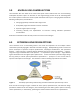
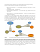
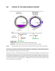
Figure 2 The global production communities freely “mix ‘n match” lenses and cameras In 2011 Canon leveraged the vast accumulation of experiences in the broadcast television optics business and that of the now firmly established Canon EOS system to enter the digital cinema world with a family of high-end professional digital cinema lenses (both primes and zooms) and cameras — the Canon Cinema EOS system.
3.0 LIMITATIONS OF THE CURRENT EOS SYSTEM Assessing the current EOS system in the context of future considerations exposes some limitations as follows: 1. Insufficient flexibilities in mount diameter and back focus distance to accommodate all of the increasingly diverse requirements in zoom and prime lenses 2. Limited speed of the electronic communication between lens and camera 3. Limited electronic channels between lens and camera to accommodate new operational aspirations 4.
5.0 AN IDEAL LENS-CAMERA SYSTEM Three decades after the debut of the Canon EOS system Canon believes that new and broadening marketplace dynamics require an extension to the original design premise of the EF interchangeable lens-camera system. An ideal lens-camera system intended for future years in imaging would include the following contemporary considerations: 1. Emerging popularity of the full frame image sensor 2. Anticipated progressive elevation of sensor resolution 3.
In that context, seeking the ideal lens for a given shooting application must envisage broadening flexibilities in optical and system developments according to the following: 1. Higher Optical Performance — to accommodate multiple future enhancements in camera performance 2. Increased optical speed — for specific lenses 3. Enhanced Operational Specifications — such as focal length ranges, maximum aperture, and their controls 4.
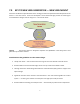
7.0 KEY TO NEW LENS GENERATION — NEW LENS MOUNT Central to the effective implementation of the strategy to extend the potential of the EOS system for the future is a new lens mount. Canon has developed a mount that holds high promise of sustaining far more flexible lens designs over the long term — the new RF mount. Figure 6 The new lens mount is designed to empower new flexibilities in lens design and a new generation of mirrorless cameras Considerations that guided the new lens mount design: 1.
8.0 DETAILS OF THE NEW CANON RF MOUNT Figure 7 Showing new RF mount (on the right) side by side with the existing EF mount (on the left) RF mount is a new mount that maintains the advantages of a fully electronic large-diameter EF mounts while additionally offering an optimal diameter, flange back, and back focus to more fully capitalize on optical characteristics of a full-frame mirrorless systems. Like the EF mount, a 3-tab bayonet mount is used in the RF mount.
The reduction from a 44mm flange back distance in the EF mount system to the 20 mm of the new RF mount system opens important additional degrees of freedom in lens designs. The pivotal innovation offered by this short distance, combined with the large 54 mm diameter RF mount — is the freedom to deploy large diameter optical elements at the very rear of the lens and closer to the large image sensor. This adds new optimization capabilities to the lens-camera imaging interface.
9.0 THE CHALLENGE OF MANAGING LENS ABERRATIONS Optical aberrations are an inescapable reality of each and every element within all lenses. The wellknown Seidel monochromatic aberrations are image defects associated with the fundamental behavior of light rays—of all wavelengths — passing through a lens element. These monochromatic aberrations include spherical aberration, coma, astigmatism, curvature of field and geometric distortion.
Two key dimensions play a significant role in the quality of the final image projected on to the image sensor — they are the back focus distance and the diameter of the final lens element. Figure 9 is a simplistic illustration of their cumulative effect on the angle of the ray bundle landing on the extremities of the image sensor. The colored circles identify ray bundles affecting image performance in the image central zone (red) and in the image extremities (blue).
10.0 10.1 NEW CONCEPTS UNDERLYING RF LENSES New Feature Unique to RF Lenses The new RF lenses represent a quite radical step forward in lens designs that anticipate the future imaging needs of an increasingly sophisticated end user. 10.1.1 Control Ring A significant new innovation is incorporated into the design of these lenses — a special knurled control ring, which in the initial RF lens embodiments is positioned at the very front of the lens — before the focusing control ring, as shown in Figure 11.
10.1.3 Focus Ring Rotation Direction Change The RF lenses all incorporate an ability to choose the direction of rotation of the manual focus control. In place of a direct mechanical connection from focus control ring to the actual focusing optics, through a threaded, all mechanical helicoid, the system uses a focus ring connected to a series of many very fine, electronic contacts. There's no direct, mechanical connection at all to the group(s) of elements that move the focusing element.
11.1 RF28-70mm F2 L USM RF28-70 F2 L USM is a large-diameter, standard L zoom lens with a bright F2.0 constant aperture across the entire zoom range — the new 28-70mm F2. The lens is intended for professional photographers, high-end amateurs, and low-light moviemaking. It embodies high-speed auto focus functionality, and a Control Ring for functional assignment of exposure controls. Figure 12 The new RF28-70 F2 L USM — a compact 28-70mm F2.
The new RF mount made possible a zoom lens having an ultra-large dimeter and a constant F2.0 aperture across the entire zoom range. The F2.0 maximum aperture creates an excellent creative bokeh. Figure 14 Showing the operational controls on the RF28-70mm F2 L USM lens This remarkable zoom lens is represents a significant step forward in terms of the F2.0 constant aperture, generous zoom range, and a size and weight that would not have been possible in an EF lens. It is ideal for handheld shooting.
11.1.1 MTF Characteristics of the RF28-70mm F2 L USM Lens The MTF curves in Figure 15 show the behavior of this lens measured at four distances from the image center. Two spatial frequencies are used — one, at the low 10 line pairs per millimeter (LP/mm) which is an important measure of the contrast of the lens, and the second is at a higher 30 LP/mm which indicates resolving power. Two separate measurements are made for each at right angles to each other.
11.1.2 MTF of RF28-70mm F2 L USM and Equivalent EF Zooms Figure 16 shows the MTF curves for the new EF28-70mm F2 L USM on the right compared with those of two established EF zoom lenses — with all three lenses set at maximum aperture. Of special note are the following: 1. 10 Lp/mm Sagittal of the new F2 lens is very close to that of the EF24-70mm f/2.8L II USM lens (slightly better at maximum image height) and is much higher than the EF24-70mm f/4L IS USM lens at max height 2.
Figure 17 shows the MTF curves for the telephoto end of all three zoom lenses. 1. 10 Lp/mm Sagittal is slightly higher than both EF lenses at the far corners of the image 2. 10 Lp/mm Meridional is essentially equivalent to that of the EF24-70mm f/2.8L II USM but is higher than that of EF24-70mm f/4L IS USM 3. 30 Lp/mm Sagittal is higher than both EF lenses at the 22 mm height 4. 30 Lp/mm Meridional is essentially equivalent to that of the EF24-70mm f/2.
11.2 RF50mm F1.2 L USM This is a large diameter standard single-focus lens employing the new standard RF mount. At its maximum aperture of F1.2 the lens maintains high sharpness at image center with well controlled falloff of MTF toward the image extremities. The lens is designed to extend the creative photo expressiveness for professional photographers and high-end amateurs. Figure 18 The new RF50mm F1.
The lens deploys three high-refraction aspheric elements — shown in green in Figure 19. Chromatic aberrations are minimized using the UD element (dark green). Flare and ghosting are particularly well controlled using Canon’s Super Spectra Coatings — with the Air Sphere Coating (ASC) technology on one critically positioned lens element shown in Figure 19.
11.2.1 MTF Characteristics of the RF50mm F1.2 L USM lens compared to EF Lenses Figure 21 shows the MTF characteristics of the RF50mm F1.2 L USM lens at the maximum relative aperture setting of F1.2. Figure 21 The 10 and 30 Lp/mm MTF curves for RF50mm F1.2 L USM Figure 22 Comparing the MTF characteristics of the RF50mm F1.
1. 10 Lp/mm Sagittal of the RF50mm F1.2 L USM lens maintains a significantly higher MTF across the total image height compared to both EF lenses (and especially compared to the EF50mm f/1.2L USM) 2. 10 Lp/mm Meridional exhibits an excellent MTF characteristic compared to both EF lenses 3. 30 Lp/mm Sagittal exhibits a higher and more controlled MTF across the total image height than the two EF lenses 4. 11.3 30 Lp/mm Meridional curve for RF50mm F1.
Figure 24 Showing the fourteen groups made up of a total of eighteen lens elements in the RF24105mm F4 L IS USM lens Strategic disposition of three aspheric lens elements (shown in light green in Figure 24 helps correct for astigmatism, spherical aberration, and geometric distortion. The UD lens element shown in dark green helps minimize both lateral and longitudinal chromatic aberrations.
Because the focusing element (“focus lens” in Figure 24 above) is small and lightweight the focusing actuator deploys a Nano USM (new Thin-type). This motor uses the basic Ultrasonic principle, of extremely controlled, fine vibrations produced by running current through a specific metal device. In this case, the "device" looks almost like a tiny metal bandage, with little projecting nubs on either side — Figure 26.
Figure 28 shows the MTF curves for the new RF24-105mm F4 L IS USM on the left compared with those of two established EF zoom lenses — for the wide end of their respective zoom ranges. Of special note are the following: 1. 10 Lp/mm Sagittal is slightly lower than that of the EF24-105mm f/4L IS II USM lens except at the extreme corners of the image 2.
Figure 29 shows the MTF curves for the new RF24-105mm F4 L IS USM on the left compared with those of two established EF zoom lenses — for the wide end of their respective zoom ranges. Of special note are the following: 1. 10 Lp/mm Sagittal for RF24-105 F4 L IS USM is slightly lower across the image height than that of the EF24-105mm f/4L IS II USM except at maximum image height 2.
11.4 RF35mm F1.8 MACRO IS STM RF35mm F1.8 MACRO IS STM is a wide angle macro lens employing the new standard RF mount having a maximum aperture of F1.8 and a 0.5x magnification. It has a minimum aperture of F22. This is a moderate wide-angle lens with a compact overall design, ideally suited to traditional candid street photography and low-light imaging. It combines beautifully with the smaller mirrorless camera as a lightweight, travel and location oriented lens for serious enthusiasts.
The lens has the new control ring — with 54 clicks per revolution. It has a high performing optical image stabilization system with shake-correction allowing hand-holding at shutter speeds up to 5-Stops slower than would normally be possible — impressive for a lens having a brightness of F1.8. In two key areas a notable improvement was implemented in this new 35 mm lens compared to the well-known EF35mm f/2 IS USM lens. The overall length of the lens’s optical path is shortened from 105 mm to 80.
Figure 33 Figure 34 EF lenses MTF curves for RF35mm F1.8 MACRO IS STM lens MTF characteristics of the new RF35mm F1.8 MACRO IS STM lens compared to two 35mm The new RF35mm F1.8 MACRO IS STM has remarkably similar MTF characteristics to those of the excellent EF35mm f/1.4L lens. But it is a more compact and lightweight lens and has a macro shooting capability at f/1.8 brightness that cannot be matched by any EF lens.
1. 10 Lp/mm Sagittal for the new RF35mm F1.8 MACRO IS STM lens maintains a slightly higher MTF across the total image height compared to the EF35mm f/2 IS USM and is much lower than that of the EF35mm f/1.4L II USM 2. 10 Lp/mm Meridional exhibits a lower MTF than both EF 35mm lenses 3. 30 Lp/mm Sagittal for the RF35mm F1.8 MACRO IS STM is somewhat similar to that of the EF35mm f/2 IS USM out to 15mm height but slightly higher at maximum image height but is not as well controlled as the EF35mm f/1.
12.1 Mount Adapter EF-EOS R Figure 35 12.
12.3 Drop-In Filter Mount Adapter EF-EOS R Figure 37 Drop-In Filter Mount Adapter EF-EOS R showing the various options for the drop-in optical filters 13.0 EOS R LENS-CAMERA SYSTEM The EOS R system incorporates a variety of operational empowerments that have been made possible because of new innovation in the new lens series and the high-speed electronic communication between the lens and the camera. 13.
In the new EOS R system the lens embodies new technologies that combine with the IS system in the camera to implement an augmented control over the image blurring that can be caused by shaking and vibration of the lens-camera system. This is empowered by an interactive data communication between the two. Within the lens a dual gyro sensor system detects any inadvertent physical movements of the system and this data is reported across lens-camera communication to the DIGIC 8 processor.
13.2 Digital Lens Optimizer (DLO) System The Digital Lens Optimizing system is built into the EOS R camera and is intended to implement realtime corrections for a number of optical aberrations and distortions encountered over a wide range of shooting conditions. Before the light rays reach the CMOS image sensor they pass through the multielement lens and various filters as illustrated in Figure 40.
Figure 42 Showing the stored data files on lens aberrations and the real-time lens operational controls communication across to the DLO engine within the EOS R camera The DLO system can implement corrections for the following 1. Resolution loss due to cumulative aberrations 2. Resolution loss due to diffraction 3.
In the EOS R system, Digital Lens Optimizer can be applied in-camera when the RAW files are converted to JPEG image files, and users can expect improvements in fine detail and resolution, especially with subjects having lots of inherent detail (think grass and foliage in landscapes, textures in fashion fabrics, etc.). If RAW images are recorded and then processed in Canon’s Digital Photo Professional software, similar benefits can be applied in processing the images. 13.
Figure 44 Showing the separate processing of the dual pixel data from the image sensor — for video and for Auto Focus — at the entry stage of the Digic 8 processor Figure 44 illustrates the manner in which the sets of dual pixel outputs from the CMOS image sensor are sent to the DIGIC 8 processing microcircuit that was developed by Canon.
It can range across the image plane according to the discrete manually “Selectable AF Points” outlined in Figure 45. There are 87 positions horizontally (covering 88% of the image width) and 65 positions vertically (covering 100% of the image height) for these selectable AF points. This ensures very precise auto focus operation.
13.4 Comparison of EOS R Lens-Camera System with EF Lens and DSLR A sense of the significant compactness that the EOS R camera system can offer is shown in the outline drawing of Figure 46 which compares it to the Canon EOS 5D Mark IV.
A more dramatic illustration is shown in Figure 47 — which effectively conveys how the new lens and mount have very effectively shortened the overall length of the lens-camera system.
14.0 SUMMARY The EOS system is hugely established across the globe and continues to move in new directions — as the lines between still and motion imaging blur and as lens-camera image quality steadily increases with every generation. Applications of still and motion imaging have seen extraordinary advances at all levels — from amateur all the way to the highest professionals.