PUB.
Safety Instructions Be sure to read these instructions in order to operate the product safely. Follow these instructions to prevent injury or harm to the operator of the product or others. 2 WARNING Denotes the risk of serious injury or death. • Stop using the product in any case of unusual circumstances such as the presence of smoke or a strange smell. • Do not touch any exposed internal parts. • Do not get the product wet. Do not insert foreign objects or liquids into the product.
CAUTIONS Follow the cautions below. Otherwise physical injury or property damage may result. • Do not leave the product in places exposed to extremely high or low temperatures. The product may become extremely hot/cold and cause burns or injury when touched. • Only mount the product on a tripod that is sufficiently sturdy. • Do not look at the screen for prolonged periods of time. This may induce symptoms similar to motion sickness.
Table of Contents 5 Safety Instructions 2 1. Introduction 9 About this Manual 9 Conventions Used in this Manual 9 Supplied Accessories 10 Names of Parts 11 Camera 11 2.
Zoom 68 Selecting the Zoom Mode 68 Selecting the Zoom Controls 68 Using the Zoom Ring 69 Using the Zoom Rockers 69 Focus 73 Manual Focus 73 Push AF/MF 76 AF-Boosted MF 76 Continuous AF 77 Changing the AF Frame Type and Position 78 Face Detection 78 Focus Limit and Macro Shooting 80 Image Stabilization 81 Onscreen Markers, Zebra Patterns and False Color 82 Displaying Onscreen Markers 82 Displaying Zebra Patterns 84 Displaying False Color 84 Setting the Time Code 85 Selecting the Time Code Mode 85 Selecting
5. Playback 129 7.
1 Introduction 9 About this Manual Thank you for purchasing the Canon XF605. Please read this manual carefully before you use the camera and retain it for future reference. Should the camera fail to operate correctly, refer to Troubleshooting (A 207). Before Using the Camera • Before making important recordings for the first time, make test recordings using the video configuration(s) you plan to use to check that the camera operates correctly.
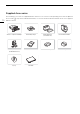
Supplied Accessories Supplied Accessories 10 The following accessories are supplied with the camera. For accessories sold separately, please refer to Optional Accessories (A 222). Unless indicated otherwise, accessories mentioned in this manual are the ones supplied with the camera. CA-CP200 L Compact Power Adapter CG-A20 Battery Charger BP-A30 Battery Pack (incl. terminal cover) Lens Hood with Lens Barrier Microphone Holder (incl.
Names of Parts Names of Parts Camera 11 1 3 1 2 3 4 4 5 6 7 Focal plane mark × (headphone) terminal (A 97, 134) Lens hood (A 28) Lens barrier switch (A 41) 2 8 5 6 7 8 Focus ring (A 73) Zoom ring (A 69) Iris ring (A 63) Protective cover for audio controls (A 91)
Names of Parts 2 3 4 5 6 7 12 8 1 9 10 11 12 13 18 1 2 3 4 5 6 7 8 9 10 11 12 13 14 15 16 17 19 20 21 ND FILTER +/– buttons (A 61) PUSH AF/MF (momentary autofocus) button (A 76) FOCUS (focus mode) switch (A 73) POWERED IS button (A 81)/ Assignable button Camera 1 (A 115) FULL AUTO switch (A 42) PEAKING button (A 75)/ Assignable button Camera 2 (A 115) MENU button (A 25) FUNC (main functions) button (A 50)/ Assignable button Camera 8 (A 115) INFRARED switch (A 110) STATUS (display status screen)
Names of Parts 2 1 4 1 2 3 4 5 6 5 Strap mount MIC (microphone) terminal (A 93) INPUT 1/INPUT 2 terminal (XLR) (A 93) Exhaust ventilation outlet (A 40) USB (HOST) terminal Used for future functionality expansion. REMOTE A terminal For connecting the RC-V100 Remote Controller (A 111) or commercially available remote controllers.
Names of Parts 1 2 3 4 5 6 14 7 8 9 12 10 11 13 14 15 16 1 2 3 Accessory shoe Grip zoom rocker (A 69) MAGN. (magnification) button (A 75)/ Assignable button Camera 6 (A 115) 4 u (review recording) button (A 48)/ Assignable button Camera 5 (A 115) 5 Multi-function shoe (A 30) Using accessories with screws may damage the multi-function shoe. 6 Multi-function shoe cover (A 30) 7 Strap mount 8 Accessory socket For mounting accessories with 1/4"-20 screws (7.5 mm (0.30 in.) deep).
Names of Parts Locking the camera’s controls (key lock) You can set lock lever (A 14) or the KEY LOCK switch to C (key lock) to lock all the camera’s buttons* and switches. This is useful in preventing settings from being changed due to inadvertently pressing one of the buttons. Set lock lever (A 14) or the KEY LOCK switch back to D to reactivate the controls. When the camera’s controls are locked, you can still operate the camera using an RC-V100 Remote Controller or the Browser Remote application.
Names of Parts 1 16 2 3 4 1 2 Built-in speaker (A 134) Located below the space where the LCD monitor is stored. Socket for tripod's anti-rotation pin (5 mm (0.20 in.) deep, x2) For tripods with 1/4"-20 mounting screws. 5 3 4 5 Screw hole for 1/4"-20 mounting screws (7.5 mm (0.30 in.) deep) Socket for tripod's anti-rotation pin (5.5 mm (0.22 in.) deep) For tripods with 3/8"-16 mounting screws. Screw hole for 3/8"-16 mounting screws (10 mm (0.39 in.
Names of Parts 5 6 1 17 2 3 4 7 1 2 3 4 Microphone lock screw (A 93) Microphone holder (A 93) Microphone cable clamp (A 93) Built-in stereo microphone (A 91) 8 5 6 7 8 Front tally lamp (A 41) Infrared light (A 110) Air intake vent (A 40) Assignable button Camera 11 (A 115)
Names of Parts 5 6 7 8 9 18 1 10 11 12 13 14 2 15 16 17 3 18 19 4 20 1 2 3 4 21 22 LCD monitor with touch screen (A 23) SLOT SELECT (SD card selection) button (A 33) SD card access indicators (SD2/SD3) (A 32) SD card slots (A 32): SD CARD2 (top) and SD CARD3 (bottom) In this manual, SD cards in each slot are referred to as “SD card A” and “SD card B”, respectively.
2 Preparations 19 Preparing the Power Supply You can power the camera using a battery or a power outlet. Even when a battery is attached, if the camera is connected to a power outlet, it will not draw power from the battery. Using a Battery You can power the camera using the BP-A30 Battery Pack or the BP-A60 Battery Pack. Both battery packs are compatible with Intelligent System so you can check the approximate remaining battery usage time (in minutes) on the screen.
Preparing the Power Supply 20 NOTES • We recommend charging the battery in temperatures between 10 ºC and 30 ºC (50 ºF and 86 ºF). Outside the temperature range of 0 ºC to 40 ºC (32 ºF to 104 ºF), charging will not start. • If there is a malfunction with the battery charger, AC adapter or battery, the charge indicator will go out and charging will stop. • For handling precautions regarding the battery, refer to Handling Precautions (A 219).
Preparing the Power Supply Checking the Remaining Battery Charge When the camera is turned on, you can check the approximate remaining battery usage time (in minutes) by looking at any recording/playback screen or the [B System Setup] status screen (A 202). You can also check the approximate charge level on the battery itself. Press the CHECK button on the battery. An indicator will light for approximately 3 seconds and show the approximate remaining battery charge.
Preparing the Power Supply Using a Power Outlet 22 You can also power the camera directly from a power outlet using the CA-CP200 L Compact Power Adapter (AC adapter). While the camera is powered using a power outlet, you can replace the battery pack even when the camera is turned on. 1 Connect the power cord to the AC adapter and plug it into a power outlet. 2 Connect the AC adapter’s DC plug to the DC IN terminal on the camera.
Using the LCD Screen Using the LCD Screen This section explains how to adjust the LCD monitor. You can adjust the direction of the screen as shown below, as well as image settings such as brightness or contrast. Additionally, you can use the touch screen to select the subject or perform a variety of settings using direct touch control (A 49). 1 Open the LCD monitor 180 degrees (햲) and adjust to the desired angle (햳). 2 You can also place the LCD monitor so that it faces the subject.
Date, Time and Language Settings Date, Time and Language Settings Setting the Date and Time 24 You will need to set the date and time on the camera the first time you power it on, or after the camera's settings have been reset. The [Date/Time] screen will appear automatically when the camera’s clock is not set. Refer to Using the Menus (A 25) for instructions on how to operate the menus. 1 Select the desired time zone* using the joystick, and confirm by pressing the joystick itself.
Using the Menus Using the Menus Many of the camera’s functions can be adjusted using the menus. In CAMERA mode, you can also register frequently used menu settings in a customized menu (My Menu) for easy access. For details about the available menu options and settings, refer to Menu Options (A 185). MENU button Press the button to open the setup menus and then press again to close the menu after adjusting desired settings.
Using the Menus • You can also touch the desired page or menu item. • Going forward, this operation will be referred to as “press SET” in this manual. 4 Select the desired menu item ([Language H], in the example) and then press SET. • Push the joystick left/right to scroll through the menu pages. Moving left/right from the first/last page will move to the previous/next setup. • Push the joystick up/down to move the cursor over the menu items on the page.
Using the Menus 3 Move the menu setting to the desired position and press SET. Removing Menu Settings 1 Select > [¥ My Menu] > Desired menu page > [Edit] > [Delete]. 2 Select the menu setting you want to remove and then select [OK]. Resetting All the My Menu Sets Reset all the menu settings registered to the currently selected My Menu set. Select > [¥ My Menu] > Desired menu page > [Edit] > [Reset All] and then select [OK].
Preparing the Camera Preparing the Camera This section details how to prepare the camera for the first time, including how to attach the microphone holder and the lens hood, as well as how to adjust the viewfinder. 28 Attaching the Microphone Holder To the Right Side of the Handle Unit 1 Attach the microphone holder to the handle unit. 2 Use a commercially available Phillips head (“crosshead”) screwdriver to secure it firmly with the 2 M4 bolts.
Preparing the Camera Lens Diffraction Correction The image produced may not be as sharp at certain apertures (lens diffraction), in which case, you can apply a correction to compensate as necessary. 29 1 Turn on the camera in CAMERA mode. 2 Select > [v Camera Setup] > [Diffraction Correction] > [On]. • The camera will apply the correction for the attached lens to all future recordings.
Preparing the Camera Attaching and Removing the Eye Cup 30 Eye cup Attach the eye cup so that it covers the rubber rim of the viewfinder unit. To remove the eye cup, pull it gently in a “peeling off” motion from the bottom up. • For left eye use, attach the eye cup so that the protruding part faces the opposite side. Viewfinder unit IMPORTANT • Pointing the viewfinder lens at the sun or other strong light sources may cause damage to internal components.
Preparing Recording Media Preparing Recording Media The camera records clips, photos and other files on SD cards*. The camera has two card slots, and recording on two cards is possible (A 35). Initialize cards (A 32) when you use them with this camera for the first time. * The SD card is used also to save/read other files such as custom picture files. Compatible Recording Media The following types of memory card can be used with this camera.
Preparing Recording Media Inserting and Removing an SD Card 1 Wait until the SD CARD access indicator is off or is illuminated in green. 32 2 Open the card compartment cover. 3 Insert the card straight, with the label facing the side of the operation buttons, into the SD card slot until it clicks. SD CARD indicator • You can use two cards, one in each card slot. • To remove the card, make sure the SD CARD indicator is off and then push the card once to release it.
Preparing Recording Media NOTES • If you set an assignable button to [Initialize Media] (A 115), you can press the button to open the [Initialize Media] submenu. 33 Setting a Card’s Volume Label You can set the volume label for SDXC cards used for recording (only in CAMERA mode, when recording XF-AVC clips), in order to make it easier to identify and organize them later. 1 Select > [Æ Recording/Media Setup] > [Volume Label] > Desired option. 2 Initialize the card (A 32).
Preparing Recording Media Recovering Recordings 34 Some actions, such as suddenly turning off the camera or removing the card while data is being recorded, can cause data errors in the recorded file. You may be able to recover recordings with corrupted data using the following procedure. 1 Switch to MEDIA mode and open the index screen with the recordings you wish to recover (A 129). 2 Select the desired recording (with the icon). 3 Press SET to open the file menu and select [Recover] > [OK].
Selecting the Video Recording Method Selecting the Video Recording Method This camera features various recording modes, as well as video recording methods using two cards. You can also stream the audio/video while recording it on a card (A 175). Below is an overview. For details, refer to each function’s section. Recording modes You can select the video recording method for the card selected for recording. [Recording Mode] Description A [Normal Recording] Normal recording.
Selecting the Video Recording Method Available simultaneous recording configurations Second card recording function 36 Recording mode Off Proxy Recording Sub Recording Audio Recording Relay Recording Double Slot Recording Normal Recording Ü Ü Ü Ü Ü Ü Slow & Fast Motion Recording Ü – – – – – Pre-recording Ü Ü Ü – Ü Ü Frame Recording Ü – – – Ü Ü Interval Recording Ü – – – Ü Ü Continuous Recording Ü – – – – – • Simultaneous recording is available only with nor
Setting the File Name for Recordings Setting the File Name for Recordings This section explains how to set the file names for XF-AVC clips, MP4 clips and photos. 37 XF-AVC Clips File Names The camera allows you to change several settings that determine the clip file name of recorded XF-AVC clips (only in CAMERA mode). For more details on how to enter characters, see Entering text and numbers (A 27). The basic file name structure is as follows.
Setting the File Name for Recordings To set the reel number or initial clip number 1 Select > [Æ Recording/Media Setup] > [Metadata] > [Reel Number] or [Clip Number] > [Change]. • To return to initial settings, select [Reset] instead. 38 2 Enter the reel/clip number using the data entry screen (A 27). To set the user-defined field 1 Select > [Æ Recording/Media Setup] > [Metadata] > [User Defined] > [Change]. • To return to initial settings, select [Reset] instead.
Setting the File Name for Recordings Options [Reset]: [Continuous]: Recording numbers will restart from 100-0001 every time you insert a new card. If a card already contains previous recordings, numbers will continue from the number following that of the last MP4 clip/photo on the card. Recording numbers will continue from the number following that of the last MP4 clip/photo recorded with the camera. This setting is the most convenient for managing files on a computer.
Using the Fan Using the Fan The camera uses a cooling fan to lower the camera’s internal temperature. In CAMERA mode, you can change the fan's operation mode from the menu. In MEDIA mode, the fan runs at all times. 40 Setting the Fan’s Operation in CAMERA Mode 1 Select > [B System Setup] > [Fan Mode] > Desired option. Options for [Fan Mode] [Automatic]: [Always On]: The fan runs while the camera is not recording and is automatically turned off while the camera is recording.
3 Recording 41 Recording Video and Photos This section explains the basics of recording clips* and photos. For details on recording audio, refer to Recording Audio (A 91). * “Clip” refers to a single movie unit recorded with a single recording operation. You can also include metadata and News Metadata (A 103) with the clip. Recording Tally lamp Power indicator SD card access indicator 1 Open the lens barrier. 2 Press the Q switch and set it to ON.
Recording Video and Photos IMPORTANT • Be sure to save your recordings regularly, especially after making important recordings. Canon shall not be liable for any loss or corruption of data. 42 NOTES • If you record using metadata or News Metadata settings, those settings will be recorded with the clip. For more details, refer to Using Metadata (A 102).
Recording Video and Photos Onscreen Displays Refer to this section for an explanation of the various screen displays that appear in CAMERA mode. You can use the custom display function (A 191) to turn off individual onscreen displays if they are not required. The menu item that controls each display is given in the following tables (1: indicates a menu item under [Custom Display 1] and 2: indicates a menu item under [Custom Display 2]).
Recording Video and Photos Left side of the screen Icon/Display Description , 44 1: [Zoom Indicator], [Zoom Position] Focus mode (A 73). 1: [Focus Mode] Z 00/00 A, @ , Custom Display Zoom (A 68). Face AF (A 78). , , Digital tele-converter (A 68) 1: [Tele-converter] TL-U58, WA-U58 Conversion lens optimization (A 72) 1: [Conversion Lens] ¯,°,± Image stabilization (A 81). 1: [Image Stabilizer] ; ,= Infrared recording and infrared light (A 110).
Recording Video and Photos Icon/Display 4 Description Double slot recording (A 35). Custom Display 2: [Recording Mode] Recording operation STBY, ÜREC Clip recording: record standby, recording. S&F STBY, S&F ÜREC Slow & fast motion recording (A 105): record standby, recording. PRE STBY, PRE ÜREC Pre-recording (A 107): record standby, recording. FRM STBY, FRM ÜREC, FRM ÜSTBY Frame recording (A 107): record standby, recording.
Recording Video and Photos Icon/Display Description Custom Display Audio level meter (A 95). 2: [Audio Level Indicator] Headphone volume (A 134). – 46 ×00, Date/time 2: [Date/Time] CH0/CH0, CH0+CH0/CH0+CH0 E 1/0000.00, 000.00°, Audio output channels (A 153). 2: [Monitor Channels] Audio limiter (A 96). 2: [Audio Level Indicator] Shutter speed (A 57). 1: [Shutter] 000.00Hz Bottom and center of the screen Icon/Display Description Custom Display A001C001 to Z999D999 Clip identification.
Recording Video and Photos CAMERA mode Display level1 [DISP Level 1] [DISP Level 2] 2 [DISP Level 3]2 Options Description [All Displays] All onscreen displays at a larger size. [All Displays (Periph. Border)] All onscreen displays at a smaller size, more appropriate for use with the peripheral border. [Main Recording Displays] Only the onscreen displays most relevant for shooting. [Only FUNC/MENU] Only markers, focus frames, and video scopes are displayed.
Recording Video and Photos Reviewing a Recording You can review all or part of the last clip recorded even with the camera set to CAMERA mode. 48 1 Select > [B System Setup] > [Review Recording] > Desired option. 2 After you finish recording a clip, press the u button. • The last clip that was recorded is played back for the selected duration. [Ð REVIEW] appears on the screen.
Adjusting Camera and Recording Settings Adjusting Camera and Recording Settings Using direct touch control, you can perform a variety of settings (camera, recording, assistance functions, etc.) in CAMERA mode. White balance and exposure related settings can also be modified with the direct setting mode, using the FUNC button. Performing Basic Settings with Direct Touch Control With direct touch control you can change commonly used settings such as camera and recording settings and assistance functions.
Adjusting Camera and Recording Settings Changing Camera Settings 50 1 Touch the setting you want to adjust, then select the desired value/ setting. • Once the settings menu is displayed, touch to select the desired value/setting as needed. • When the slider appears, drag the slider left/right or touch the / buttons to adjust the desired value. 2 Touch K.
Adjusting Camera and Recording Settings • If you set an assignable button to [White Balance], [Iris], [ISO/Gain] or [Shutter] (A 115), you can press the button to enter direct setting mode with the respective function highlighted.
Video Recording Configuration: Video Format, System Frequency, Resolution and Frame Rate Video Recording Configuration: Video Format, System Frequency, Resolution and Frame Rate 52 When recording media, you can set the video configuration used for primary clips with the following procedures. Select the main recording format (video format, color sampling, bit depth), primary resolution/bit rate and frame rate settings that best match your creative needs.
Video Recording Configuration: Video Format, System Frequency, Resolution and Frame Rate Selecting the System Frequency You can change the system frequency also in MEDIA mode if you want to play back clips from a card recorded with a different system frequency setting. 1 Select > [Æ Recording/Media Setup] > [System Frequency]. 2 Select the desired option. • The camera will reset and restart in the selected mode.
Proxy Clips Proxy Clips 54 While recording a primary clip on an SD card A, you can simultaneously record the same scene as a proxy clip on another SD card B. Because proxy clips have smaller files, they are suitable for offline editing. You can also use direct touch control to perform this function (A 49). Video configuration of proxy clips Primary clip Main recording format Main resolution 3840x2160, 1920x1080 XF-AVC YCC422 10 bit MP4 (H.
Sub Recording Clips Sub Recording Clips While recording a primary clip on an SD card A, you can simultaneously record the same scene on SD card B. See the following table for more details on the video configuration for sub recording clips. For more details on audio, see Recording Audio (A 91). You can also use direct touch control to perform this function (A 49).
Sub Recording Clips Video configuration of sub recording clips Primary clip 56 Main recording format MP4 (HEVC) YCC420 10 bit Main resolution/bit rate MP4 (H.264) 3840x2160 YCC420 8 bit 1920x1080 Frame rate 170 Mbps 59.94P, 50.00P 100 Mbps 29.97P, 25.00P, 23.98P 3840x2160 1920x1080 Sub recording format, resolution and bit rate 35 Mbps 59.94P, 50.00P 150 Mbps 59.94P, 50.00P, 29.97P, 25.00P, 23.98P 35 Mbps 59.94P, 50.00P MP4 (HEVC) YCC422 10 bit MP4 (HEVC) YCC420 10 bit MP4 (H.
Shutter Speed Shutter Speed You can set the shutter speed according to the shooting conditions. For example, you may want to set slower shutter speeds in darker environments. The camera offers the following modes. You can also perform this function remotely using Browser Remote on a connected network device (A 181). [Speed]: Allows you to set the shutter speed (in fractions of a second). You can select the increment to use when adjusting the shutter speed between 1/3-stop and 1/4-stop increments.
Shutter Speed Changing the Shutter Speed Value When the shutter speed mode is set to a mode other than OFF or automatic, you can set the shutter speed manually. 58 1 Select the shutter speed mode (A 57). 2 For [Speed] only: Select > [v Camera Setup] > [Shutter Increment] > [1/3 stop] or [1/4 stop]. 3 Adjust the shutter speed, angle value or clear scan frequency using the direct setting mode (A 50). • You can also use direct touch control (A 49).
ISO Speed/Gain ISO Speed/Gain You may want to adjust the brightness of the image according to the shooting conditions. You can choose between manual and automatic settings. The camera offers 3 gain levels (L/M/H) that you can select simply by changing the position of the ISO/GAIN switch. By choosing manual settings you can change the ISO speed or gain value to adjust the sensitivity of the sensor. You can also perform this function remotely using Browser Remote on a connected network device (A 177, 181).
ISO Speed/Gain Manual ISO Speed/Gain Value You can set beforehand 3 gain levels and then select quickly which one to apply simply by changing the position of the ISO/GAIN switch. 60 1 Set the AGC switch to OFF. 2 Set the ISO/GAIN switch to the position you want to adjust (L, M or H). Setting the ISO Speed/Gain Value for the ISO/GAIN Switch 1 Select [Gain].
ND Filter ND Filter Using the ND filter allows you to open up the aperture to obtain a shallower depth of field even when recording in bright surroundings. You can also use the ND filter to avoid the soft focus caused by diffraction when using small apertures. You can select one of 3 density levels. You can also perform this function remotely using Browser Remote on a connected network device (A 181). Press the ND FILTER + or – button to select the desired ND filter setting.
Aperture Aperture You can affect the brightness of your recordings or change the depth of field by adjusting the aperture. You can also perform this function remotely using Browser Remote on a connected network device (A 181). 62 Automatic aperture: The camera adjusts the aperture automatically. Push Auto Iris: Momentary automatic aperture. During manual aperture, press the PUSH AUTO IRIS button or other control to temporarily adjust the aperture automatically.
Aperture Manual Aperture: Changing the Aperture Value 1 Set the IRIS switch to M. 2 Select > [v Camera Setup] > [Iris Increment] > [1/3 Stop] or [1/4 Stop]. • You can also set > [v Camera Setup] > [Fine Increment] to [On] to use the smallest iris increment. Nevertheless, the aperture value displayed on the screen will be the closest value in the selected increment scale. 3 Turn the iris ring to adjust the aperture.
Aperture Exposure Compensation - AE Shift 64 Use AE shift to compensate the exposure that was set using automatic aperture, in order to darken or lighten the image. You can also perform this function remotely using Browser Remote on a connected network device (A 181). 1 Select > [v Camera Setup] > [AE Shift]. 2 Select the desired option. • The camera will attempt to adjust the exposure accordingly. • You can select one of 17 AE shift levels from –2.0 to +2.0.
White Balance White Balance The camera uses an electronic white balance process to calibrate the picture and produce accurate colors under different lighting conditions. The camera offers the following methods to set the white balance (which can be set to one of the WHITE BAL. switch positions, and switched as desired*). You can also perform this function remotely using Browser Remote on a connected network device (A 179). * Available modes will depend on the WHITE BAL.
White Balance Auto White Balance (AWB) 66 The camera constantly adjusts the white balance automatically to achieve an appropriate level. The camera will adjust the white balance if the light source changes. Set the AWB switch to ON. • The color temperature and CC value set automatically by the camera will appear at the bottom of the screen next to the icon.
White Balance White balance mode/setting ¼ (daylight) É (tungsten lamp) È (color temperature) Adjustment range Color temperature (K) 4,300 K to 8,000 K 2,700 K to 3,700 K 2,000 K to 15,000 K Color compensation (CC) value –5 to +5 –20 to +20 NOTES • You can use the > [v Camera Setup] > [C. Temp. Increment] setting to change the units for the color temperature increment to [Mired] (5-mired increments) or [Kelvin] (100-kelvin increments).
Zoom Zoom You can operate the zoom using the zoom ring or one of the zoom rockers (grip/handle). In addition, you can choose the digital tele-converter function from the menu. 68 Selecting the Zoom Mode Select > [v Camera Setup] > [Digital Zoom] > Desired option. Options [Tele-converter 6.0x], [Tele-converter 3.0x], [Tele-converter 1.5x]: The camera processes the image digitally to multiply the focal length by a factor of 6, 3 or 1.5, respectively.
Zoom Using the Zoom Ring The zoom speed depends on how fast you turn the zoom ring. 69 1 Set the ZOOM switch to RING. 2 Turn the zoom ring to zoom. • The zoom ratio is determined by the position of the zoom ring. NOTES • When you change the ZOOM switch's position from ROCKER to RING, the camera will zoom automatically to the focal length indicated by the current position of the zoom ring. • You can operate the zoom ring even when the camera's controls are locked (A 15).
Zoom Setting the Zoom Speed (Grip Zoom Rocker) > [v Camera Setup] > [Zoom Speed Level] > Desired option. • The selected speed will also be applied to the grip zoom rocker. 1 Select 70 2 Select > [v Camera Setup] > [Grip Zoom Speed] > Desired option. Options [Constant]: Select one of 16 constant zoom speeds. [Variable]: Variable zoom speed (zoom faster the harder you press). [User Setting]: You can customize up to 3 zoom speed patterns, setting the desired zoom speed for 5 individual pressure levels.
Zoom Using the Handle Zoom Rocker You can set the zoom speed of the handle zoom rocker using the menu. 71 1 Set the ZOOM switch to ROCKER. 2 Move the zoom rocker toward T to zoom out (wideangle) and toward S to zoom in (telephoto). Handle zoom rocker: Approximate zoom speeds (time required to zoom end-to-end) [v Camera Setup] > [Zoom Speed Level] [v Camera Setup] > [Handle Zoom Speed] [Low] [Normal] [High] [1] (slowest) 4 min 38 sec 2 min 1 min [16] (fastest) 4.2 sec 2.6 sec 0.
Zoom Using Conversion Lenses You can use the following conversion lenses with this camera. For details on the following accessories, refer to their respective instruction manuals. 72 Conversion Lens Focal Length Factor Minimum Focusing Distance TL-U58 Tele-converter Approx. 1.5x Approx. 130 cm (4.3 ft.) throughout the zoom range WA-U58 Wide Attachment Approx. 0.8x Approx. 60 cm (2.0 ft.) throughout the zoom range > [v Camera Setup] > [Conversion Lens] > Desired option.
Focus Focus The camera offers the following ways to focus. The camera incorporates Dual Pixel CMOS AF technology for advanced autofocus performance. You can also adjust the focus remotely using Browser Remote on a connected network device (A 181). Note that some methods allow you to operate aspects of the focus by touching the LCD screen. Manual focus: Turn the focus ring on the lens to adjust the focus.
Focus Using the Focus Assistance Functions 74 In order to focus more accurately, you can use the following focus assistance functions: Dual Pixel Focus Guide, an onscreen guide that shows you if the selected subject is in focus; peaking, which creates a clearer contrast by emphasizing the outlines of the subject; and magnification, which enlarges the image on the screen. You can use peaking and the focus guide or peaking and magnification simultaneously for greater effect.
Focus Peaking The camera offers two peaking levels. 1 Press the PEAKING button. • The peaking icon (J or K) appears on the left of the screen and outlines (contour lines) in the image that are in focus will be shown highlighted. • Press the button again to turn off peaking. • You can use direct touch control (A 49) to turn the [Peaking 1]/[Peaking 2] setting on/off.
Focus Push AF/MF 76 When the focus mode is set to manual, the camera will focus automatically as long as you hold the PUSH AF/MF button pressed down. During autofocus, holding the PUSH AF/MF button pressed down will allow you to adjust the focus manually. Press and hold the PUSH AF/MF button. NOTES • The focus will be locked when Face AF is set to [Face Only] and a face has not been detected, or when [AF Mode] is set to [AF-Boosted MF] and the focus is outside of the automatic adjustment range.
Focus Continuous AF The camera will focus automatically on a subject inside the main area of the image (approximately 80% of the screen’s length and height). 1 Set the focus mode switch to automatic. • @ appears on the screen. > [v Camera Setup] > [AF Mode] > [Continuous]. • If [AF Frame] is set to either [Large] or [Small], a white AF frame will appear on the screen.
Focus Changing the AF Frame Type and Position You can change the type and position of the AF frame that appears on the screen (except for the face detection/ tracking frame) while using one of the autofocus functions. 78 1 Select > [v Camera Setup] > [AF Frame Position] > Desired option. 2 Select > [v Camera Setup] > [AF Frame] > Desired option. Options for [AF Frame Position] [Selectable]: You can move the AF frame by touching the desired point on the LCD screen.
Focus 5 Point the camera at a person. • All detected faces will have a face detection frame. The main subject will be indicated with a face detection frame with small arrows (white when autofocus is active, gray or yellow* during manual focus). If eye detection is enabled, a frame will appear on the eyes of the main subject. • Push the joystick (left/right) to select a different person as the main subject.
Focus Tracking a Specific Subject You can have the camera track other moving subjects that are not faces and also combine the tracking function with one of the autofocus functions to let the camera focus on the desired subject automatically. 80 When [AF Mode] is set to [Continuous] and [AF Frame] is set to [Whole Area] Touch the desired subject on the LCD screen. • A double frame £ (tracking frame) is displayed and the camera will start tracking the selected subject.
Image Stabilization Image Stabilization You can use the image stabilizer to compensate for camera shake and achieve steadier shots. Select an IS mode that best fits your needs. When you are stationary and zooming in on far subjects using high zoom ratios, it is possible to compensate for a high degree of camera shake by using Powered IS.
Onscreen Markers, Zebra Patterns and False Color Onscreen Markers, Zebra Patterns and False Color 82 Using onscreen markers allows you to make sure your subject is correctly framed and is within the appropriate safe area. Zebra patterns help you identify areas that are overexposed. The false color overlay allows you to check if the exposure is correct. You can display the assistance overlays independently on the screen, SDI OUT terminal and HDMI OUT terminal.
Onscreen Markers, Zebra Patterns and False Color 2 For [Center Marker] only: Select shape. > [A Assistance Functions] > [Center Marker Type] > Desired marker Aspect Marker 1 Select > [A Assistance Functions] > [Aspect Marker] > Desired marker color or transparency of the masked area. • Select [Off] to turn off the marker. 2 Select > [A Assistance Functions] > [Marker Aspect Ratio] > Desired option. 3 For [Custom] only: Select > [A Assistance Functions] > [Marker Custom Asp.
Onscreen Markers, Zebra Patterns and False Color Displaying Zebra Patterns 84 The camera has a zebra pattern function that shows black and white diagonal stripes over areas that are overexposed. There are two types of zebra patterns and you can display both simultaneously. Zebra 1 lets you identify areas within a certain range (±5% of a specified level from 5% to 95%) while zebra 2 lets you identify areas that exceed a specified level (from 0% to 100%).
Setting the Time Code Setting the Time Code The camera generates a time code signal and records it with the recorded clips. The time code signal can be output from the SDI OUT terminal, TIME CODE terminal or HDMI OUT terminal. Depending on the frame rate used, you may be able to select between a drop frame an non-drop frame time code signal (A 86).
Setting the Time Code Selecting Drop or Non-Drop Frame 86 When the frame rate is set to 59.94P, 59.94i or 29.97P, you can select between a drop frame (DF) or non-drop frame (NDF) time code, depending on how you plan to use your recordings. With all other frame rates, the time code is set to non-drop frame (NDF) and cannot be changed. > [B System Setup] > [Time Code DF/NDF] > Desired option. • The time code display will change depending on the setting.
Setting the Time Code Setting the User Bit You can set a user bit composed of the date or the time of recording or an identification code consisting of 8 characters in the hexadecimal system. There are sixteen possible characters: the numbers 0 to 9 and the letters A to F. The user bit is recorded with clips and can be output from the SDI OUT terminal, TIME CODE terminal or HDMI OUT terminal. It can be used freely to categorize and manage recordings or to keep additional information about them.
Synchronizing with an External Device Synchronizing with an External Device 88 You can use the camera’s TIME CODE terminal to synchronize this camera’s time code to an external signal. Using the same external time code signal with multiple cameras allows you to set up a multi-camera recording. You can output the time code signal from this camera to other cameras.
Synchronizing with an External Device • When a suitable external time code signal is received, the camera’s own time code will be synchronized to it and the synchronization will be maintained even if you disconnect the cable from the TIME CODE terminal. • If the external time code signal is incorrect or there is no input signal, the internal time code set in the camera will be recorded instead.
Synchronizing with an External Device Reference Video Signal Output 90 After changing the function of the G-LOCK/SYNC terminal, you can use the camera’s video signal as a reference sync signal (tri-level HD signal) to synchronize an external device to this camera. The reference signal’s configuration is determined by the video output configuration of the SDI OUT terminal and other menu settings. 1 Select > [B System Setup] > [G-LOCK/SYNC Term.] > [HD Sync Output].
Recording Audio Recording Audio The camera features the following options for audio recording and playback. You can record audio using an external microphone/line-in device (INPUT terminal / MIC terminal), or the built-in microphone. The audio signal will be output with the video signal from the SDI OUT terminal or HDMI OUT terminal. You can record the audio signal on an external recorder.
Recording Audio Menu settings [Audio Input Selection]1 92 1 2 3 Recorded audio channels/audio sources [CH2 Input]1 CH1 CH2 CH3 CH4 [Built-in Mic] – Built-in microphone (L) Built-in microphone (R) Built-in microphone (L) Built-in microphone (R) [Multi-Function Shoe]3 – Built-in microphone (L) Built-in microphone (R) Audio terminal (commercially available accessory) Audio terminal (commercially available accessory) [CH1/CH2] [CH3/CH4] [Built-in Mic] [Built-in Mic] Menu items under the
Recording Audio - Audio will not be recorded if there is an existing WAV file with the same file name. - A maximum of 999 WAV files can be recorded. 93 Connecting an External Microphone or External Audio Input Source to the Camera To each of the INPUT terminals you can attach commercially available microphones or analog line in sources with an XLR connector. To the MIC terminal you can attach commercially available condenser microphones with a 3.5 mm stereo mini plug/external line input device (analog).
Recording Audio Selecting the Input Type for the INPUT 1/INPUT 2 Terminals Change the position of the corresponding INPUT (audio source selection) switch according to the audio device connected to the INPUT 1/INPUT 2 terminals. 94 Set the INPUT 1 or INPUT 2 switch to LINE, MIC, or MIC+48V. • When using the INPUT terminals to record to only one channel, use the INPUT 1 terminal. IMPORTANT • When using a microphone that requires phantom power, turn off the camera and set the respective INPUT switch to MIC.
Recording Audio Adjusting the Audio Recording Level You can adjust the audio recording level of the INPUT terminals, MIC terminal or the built-in microphone. You can select automatic or manual audio level adjustment, and adjust each audio channel separately or adjust CH1/ CH2 or CH3/CH4 together (when the audio level adjustment of the audio channels is linked, A 96). For the built-in microphone, the adjustments of CH1 apply to both CH1/CH2.
Recording Audio Automatic Level Control (ALC): Linking the audio level adjustment of CH1/CH2 or CH3/CH4 96 • When both CH1 and CH2 are set to the MIC terminal or INPUT terminals and to the same type of analog audio source (external line input or external microphone), you can use the > [¡ Audio Setup] > [CH1/CH2 ALC Link] or [CH3/CH4 ALC Link] setting to link the audio level adjustment of both channels. • When linked, different channels can be adjusted together.
Recording Audio Changing the Reference Level of the External Microphone (INPUT Terminals) You can select the reference level of each INPUT terminal (-18 dB or -20 dB). Select > [¡ Audio Setup] > [INPUT Reference Level] > Desired option. 97 Built-in Microphone Sensitivity You can adjust the sensitivity according as necessary. Select > [¡ Audio Setup] > [Built-in Mic Sensitivity] > Desired option. Options [Normal]: [High]: For recording audio under usual conditions.
Colors Bars/Audio Reference Signal Colors Bars/Audio Reference Signal You can have the camera generate color bars and a 1 kHz audio reference signal and output them from the following terminals. 98 Color bars Audio reference signal × (headphone) terminal LCD monitor Viewfinder SDI OUT terminal HDMI OUT terminal Ü Ü Ü Ü – – – Ü Ü Ü Color Bars The camera offers SMPTE, EBU and ARIB color bars. > [v Camera Setup] > [Color Bars] > [On]. • The selected color bars appear on the screen.
Video Scopes Video Scopes The camera can display a simplified waveform monitor or a vectorscope to check your recordings. The selected video scope is displayed on the screen and can be output to other monitoring devices as well. 99 Displaying a Video Scope 1 Select > [A Assistance Functions] > [WFM Function] > [Waveform Monitor] or [Vectorscope]. 2 Press the WFM button. • You can also use direct touch control (A 49) to turn the [Waveform Monitor]/[Vectorscope] setting on/off.
Video Scopes Options for [Type] [Line]: [Line+Spot]: 100 [Select Line]: [RGB]: [YPbPr]: Sets the waveform monitor to line display mode. The waveform of the area in the red frame is displayed in red on top of the [Line] mode waveform. The selected horizontal line (in red) will be displayed along with its waveform. Shows 3 side-by-side waveforms in an RGB parade. Shows 3 side-by-side waveforms in a YPbPr parade.
Adding Marks to Clips in CAMERA Mode Adding Marks to Clips in CAMERA Mode When the main recording format is set to XF-AVC, while recording, you can add shot marks (!) to flag an important shot or frame. After recording a clip, you can add an OK mark ($) or check mark (%) to help you identify particular clips. You can add and delete marks also in MEDIA mode (A 137, 137). Marks cannot be added to proxy clips.
Using Metadata Using Metadata The camera automatically adds metadata to the recorded clips. You can use Canon XF Utility to check and search for specific metadata. You can also add News Metadata to the recorded clips (A 103). 102 Metadata components Entering content Metadata Checking content Camera Canon XF utility Smartphone application Camera Canon XF utility Smartphone application – Ü1 – Ü Ü – GPS information: altitude, latitude and longitude.
Using Metadata Using News Metadata When recording, you can add News Metadata* to the recorded clips. Using a smartphone, you can check and edit News Metadata files. The most recently set News Metadata will be prioritized and added. See the following table for details on News Metadata settings. * Refers to a metadata file compliant with the DPP002 Metadata Exchange for News recommendation ver. 1.1.1.
Using Metadata • Automatically, > [Æ Recording/Media Setup] > [Metadata] > [Add XML File] will be set to [On], and [XML File Format] will be set to [News Metadata]. • Only the most recently transferred file can be saved. 104 Resetting News Metadata You can reset the News Metadata added to clips. 1 Select > [Æ Recording/Media Setup] > [Metadata] > [News Metadata Reset All]. 2 Select [OK].
Special Recording Modes Special Recording Modes The camera features the following special recording modes. Slow & fast motion recording: This mode allows you to change the shooting frame rate to achieve a slow motion or fast motion effect during playback. Recording audio in WAV format is also possible. Pre-recording: The camera will start recording a few seconds before you press the REC button. This is especially useful when it is difficult to predict when to start recording.
Special Recording Modes 1 2 > [Æ Recording/Media Setup] >[Main Rec Format]. > [Æ Recording/Media Setup] > [Main Resolution/Bit rate] 1 To record audio, insert an SD card into the card slot where video is not being recorded. 106 2 Select > [Æ Recording/Media Setup] > [Recording Mode] > [Slow & Fast Motion] or [S&F Clip/Audio (WAV)]. • Slow & fast motion recording is activated. [S&F STBY] appears on the screen and the shooting frame rate appears next to the frame rate setting (the playback frame rate).
Special Recording Modes Pre-recording When pre-recording is activated, the camera starts recording continuously onto a temporary memory (approx. 3 seconds) so when you press the REC button, the clip will contain also a few seconds of video and audio recorded before you pressed the button. You can also use direct touch control to perform this function (A 49). 1 Select > [Æ Recording/Media Setup] > [Recording Mode] > [Pre-Recording]. • [PRE STBY] appears on the screen.
Special Recording Modes 108 NOTES • Frame recording cannot be used simultaneously with slow & fast motion recording, pre-recording, interval recording or continuous recording. • Frame recording cannot be used when the frame rate is set to 59.94i or 50.00i. When in use, frame recording will end if the frame rate is set to 59.94i or 50.00i. • The number of frames recorded cannot be changed while recording. • Some frames at the point the recording was stopped may be recorded and added to the end of the clip.
Special Recording Modes • About the time code when interval recording is activated: - The time code mode can be set to [Regen.], or to [Preset] with [Rec Run] running mode. The time code advances by the number of frames recorded every time. - If the time code running mode was set to [Free Run] or the camera was synchronized to an external time code signal, the time code running mode will be changed automatically to [Rec Run] when interval recording is activated.
Infrared Recording Infrared Recording You can use the infrared mode to record in very dark situations using available infrared light. You can also use the camera's infrared light to make the recordings even brighter, and select the color for the picture (white or green). 110 1 Set the INFRARED switch to ON. • ; and = appear on the screen. 2 > [v Camera Setup] > [IR Rec Color] > Desired option. 3 To turn on the infrared light, select > [v Camera Setup] > [IR Light] > Desired option.
Using the RC-V100 Remote Controller Using the RC-V100 Remote Controller You can connect the RC-V100 Remote Controller to the camera in order to control the camera (including advanced recording functions) from a distance. The remote controller lets you turn the camera on, navigate the menus and remotely control the aperture and shutter speed, change picture-related settings like the knee and sharpness, and more. For details on how to connect and use the remote controller, refer to its instruction manual.
Recording Remotely Using an NU Protocol Compatible Device Recording Remotely Using an NU Protocol Compatible Device You can connect a device compatible with the NU Protocol to the camera in order to control the camera from a distance. 112 NU Protocol compatible device 1 Turn off the camera and connect the NU Protocol compatible device to the camera. 2 Turn on the camera in CAMERA mode. 3 Select > [B System Setup] > [REMOTE Term.
Web Camera Function Web Camera Function You can connect the camera to a computer using a USB cable, and use the camera as a web camera (with compatible software). Only video can be recorded while using this function. For more details about supported operative systems or software tested for use with the camera, visit your local Canon website. For more details, refer to the computer’s and the USB cable's instruction manuals.
Web Camera Function 114
4 Customization 115 Assignable Buttons The camera offers a number of assignable buttons to which you can assign various function. Assign often-used functions to the buttons you find most convenient to personalize the camera to your needs and preferences. You can find 11 assignable buttons on the camera’s body, and 4 assignable buttons on the RC-V100 Remote Controller. In most cases, the names of the buttons printed on the camera and accessories also indicate their default settings.
Assignable Buttons 3 If you selected [User Setting], select the menu setting you want to register. • The selected menu setting will be assigned to the selected button. User-selected settings will be indicated with a icon in the [ Assignable Buttons] menu. 116 4 Press the assignable button to use the assigned function as described in the following table. NOTES • You can check the [ Assignable Buttons] status screens (A 200) to see what functions are currently assigned to each button.
Assignable Buttons Description CAMERA mode MEDIA mode A [Backlight], [Spotlight] Toggles the light metering mode between [Standard] and [Backlight]/[Spotlight], respectively. Ü – 64 [IR Rec Color] Changes the color of the infrared picture between white and green. Ü – [IR Light] Only when > [v Camera Setup] > [IR Light] is set to [Toggle], turns the camcorder's infrared light on/off. Ü – [Zebra: All], [Zebra: LCD], [Zebra: VF], [Zebra: SDI], [Zebra: HDMI] Turns zebra patterns on/off.
Assignable Buttons Function name 118 Description CAMERA mode MEDIA mode A [Flicker Reduction] Turns automatic flicker reduction on/off. Ü – 58 [IP Streaming] Turns the IP streaming function on/off. Ü – 175 [Photo]1 Records a photo. Ü – 42 [Review Recording] Plays back the last clip recorded in CAMERA mode. Ü – 48 [Time Code] Opens the [B System Setup] menu page with the time code settings. Ü – 85 [Add Shot Mark]1 Adds a shot mark to the clip.
Custom Picture Settings Custom Picture Settings The camera lets you change many settings (A 123) that control various aspects of the image produced. As a set, all these settings are treated as a single custom picture file. After adjusting the desired settings to your preference, you can save up to 20 custom picture files (in the camera or on an SD card), and load them later to apply exactly the same settings (A 122).
Custom Picture Settings * This setting is found under > [/ Custom Picture] > [Edit / File]. ** ITU-R BT.2100 is a standard for a color bit depth of 10 or 12 bits. When the video configuration is set to one of the 8 bit color options, the gamma curve is approximately equivalent to this standard. 120 NOTES About the logarithmic gamma curves (Canon Log settings) - These gamma curves require post-production processing.
Custom Picture Settings Resetting Custom Picture Files 1 Select a custom picture file (A 119). 2 Select > [/ Custom Picture] > [Edit / File] > [Reset]. 3 Select a preset custom picture setting and then select [OK]. • The custom picture file will be reset to the selected values. Look Files You can register 3D LUT files (.cube format) created with Blackmagic Design’s DaVinci Resolve or other software as Look Files in the custom picture file.
Custom Picture Settings Deleting a Look File You can delete Look Files registered in custom picture files. 1 Select a custom picture file (A 119). 122 2 Select > [/ Custom Picture] > [Edit / File] > [Look File Setup] > [Delete] > [OK]. • The Look File will be deleted and the image quality adjustments will be reversed to the original settings of the selected custom picture file. Saving a Custom Picture File Copying Custom Picture Files You can copy custom picture files between the camera and SD card.
Custom Picture Settings Available Custom Picture Settings Menu items [Gamma/Color Space]1 Options / Additional information [Canon Log 3 / C.Gamut], [Canon Log 3 / BT.2020], [Canon Log 3 / BT.709], [PQ / BT.2020], [HLG / BT.2020], [BT.709 Wide DR / BT.2020], [BT.709 Wide DR / BT.709], [BT.709 Normal / BT.2020], [BT.709 Normal / BT.709], [BT.709 Standard / BT.709] Output Combination of gamma curve and color space settings that affects the overall look and color space of the image. BT.709 Normal BT.
Custom Picture Settings Menu items Options / Additional information [Black] [Master Pedestal] –50 to +50 (±0) Increases or decreases the black level. Higher settings will make dark areas brighter but decrease contrast. This setting is not available when the gamma curve component of the [Gamma/Color Space] setting is set to one of the [Canon Log 2] or [Canon Log 3] options. 124 [Master Black Red], [Master Black Green], [Master Black Blue] –50 to +50 (±0) These settings correct the color cast in blacks.
Custom Picture Settings Menu items Options / Additional information [Sharpness] [Level] –10 to +50 (±0) Sets the sharpness level of the video output signal and the recorded signal. [Detail Frequency] –8 to +8 (±0) Sets the center frequency of horizontal sharpness. Setting higher values increases the frequency, which, in turn, increases the sharpness. [Coring Level] –30 to +50 (±0) Sets the level of correction of artifacts caused by high sharpness levels (coring).
Custom Picture Settings Menu items Options / Additional information [White Balance] [R Gain], [B Gain] –50 to +50 (±0) These settings adjust the amount of white balance throughout the whole image by changing the intensity of red tones ([R Gain]) and blue tones ([B Gain]). 126 [Color Correction]1 [Select Area] [Off], [Area A], [Area B], [Area A&B] The camera detects areas with certain color characteristics (color phase, chroma, area and Y level) and corrects them when recording.
Custom Picture Settings • When an RC-V100 Remote Controller is connected to the camera, the following custom picture settings can be changed using the buttons and dials on the remote controller.
Saving and Loading Menu Settings Saving and Loading Menu Settings 128 After you adjust settings in the various menus, you can save those settings in the camera or on SD card B. You can load those settings at a later date or on another camera of the same model so that you can use that camera in the same way. Saving Menu Settings 1 Select > [B System Setup] > [Transfer Menu//] > [Save]. 2 Select [To Camera] or [To SD Card B] and then select [OK].
5 Playback 129 Playback This section explains how to play back files recorded with the camera. For details on playing back recordings using an external monitor, refer to Connecting to an External Monitor or External Recorder (A 144). Displaying the Index Screen 1 Press the Q switch and set it to ON. 2 Press the MEDIA button (A 14) • The camera is set to MEDIA mode and the clip thumbnails will appear in the index screen. • Use the joystick to move the orange selection frame.
Playback 130 NOTES • If the card contains XF-AVC clips recorded at a system frequency other than the one currently used by the camera, you will not be able to play back the clips and the clip thumbnails will not appear in the index screen. To play back such clips, change the camera’s system frequency (A 53) to match the recordings on the card. Switching Card Slots If both card slots contain a card, press the SLOT SELECT button to play back recordings from the other card.
Playback Playing Back Recordings After selecting the desired index screen, play back the desired clips, photos or audio files. You can use the touch screen, assignable buttons, or joystick to play back the recordings. Touch the thumbnail of the recording you want to play back. • Playback will start. • You can also move the orange selection frame using the joystick, and then press and hold the joystick (for approximately 1 second) to start playback.
Playback Onscreen Displays During Clip Playback 7 8 9 10 11 132 1 2 3 4 12 13 14 15 5 6 16 17 18 19 20 21 1 2 3 4 5 6 7 Fan operation (A 40) and temperature warning (A 209) LUT (A 148) Output onscreen displays (A 145) Playback button Advance 10 seconds Go back 10 seconds Recording date and time1 Frame reverse button Frame advance button Playback operation Ð PLAY Playback Ý PAUSE Playback pause 10 sec × Advance 10 seconds Ø 10 sec Go back 10 seconds Ô/Ó Frame reverse/Frame advance F FWD x5 F FWD x
Playback WAV file playback screen See Onscreen Displays During Clip Playback (A 132) for the description of onscreen displays that are common on all playback screens. 133 2 1 3 1 2 Audio file name Sampling frequency and bit depth 3 Audio level meter Clip Playback Controls The following playback types are available using the joystick and the touch screen. You can also change the position in the video using the progress bar.
Playback Adjusting the Volume 134 You can use headphones or the built-in speaker to listen to the audio during normal playback. When you connect headphones to the × (headphone) terminal, the speaker will be muted. The audio signal will also be output from the SDI OUT terminal and the HDMI OUT terminal. × (headphone) terminal 1 Select > [¡ Audio Setup] > [Headphone Volume] or [Speaker Volume]. 2 Select the desired level.
File Operations File Operations You can perform various operations on the file selected in the index screen using the file menu. Available options will depend on the type of recording selected. 135 File Menu Operations 1 Select the desired recording. 2 Press SET. • The file menu will be displayed. Available functions will differ depending on the recording. • You can also touch the screen for approximately 1 second to display the file menu. 3 Select a menu item.
File Operations Displaying Clip Information 1 Select the desired clip in the clip index screen. 2 On the file menu, select [Display Clip Info]. 136 • The [Clip Info] screen will appear. • Push the joystick left/right to move to the previous/next clip. Press the CANCEL button to return to the index screen.
File Operations Adding $ Marks or % Marks You can add an OK mark ($) or check mark (%) to XF-AVC clips to help you identify particular clips. Since clips with an $ mark cannot be deleted with the camera, you can use this mark also to protect important clips. 137 Adding an $ Mark or % Mark During Playback You can add an $ mark or % mark to a clip during playback or playback pause. 1 Set an assignable button to [Add $ Mark] or [Add % Mark] (A 115).
File Operations Deleting All the Shot Marks from a Clip 1 Select the desired XF-AVC clip in the index screen. 2 Press SET (file menu) and select [Del. All Shot Marks] > [OK]. 138 • All shot marks in the selected clip are deleted. Deleting Recordings You can delete clips, photos and audio files in WAV format. To delete clips with an $ mark, you need to delete the $ mark beforehand (A 137). 1 Select the desired file in the index screen. • Photos are selectable on the playback screen.
6 External Connections 139 Video Output Configuration The video signal output from the SDI OUT terminal or the HDMITM OUT terminal, depends on the clip’s video configuration and on various menu settings. HDMI OUT Terminal Video Output Configuration (Recording) Main recording video configuration Main recording format Resolution Frame rate 59.94P 50.00P XF-AVC MP4(HEVC) MP4(H.264) 3840x2160 29.97P 25.
Video Output Configuration Main recording video configuration 140 Main recording format Resolution Frame rate 59.94P 50.00P 59.94i4 50.00i4 1920x1080 XF-AVC MP4(HEVC) MP4(H.264) 29.97P 25.00P 23.98P 1280x720 1 2 3 4 59.94P 50.00P > [B System Setup] Video output configuration1 > [B System Setup] Video output configuration1 [HDMI Output Signal] HDMI OUT terminal2 [SDI Output Signal] SDI OUT terminal2 1920x1080P 1920x1080 1920x1080P 1920x1080 1920x1080i 1920x1080 59.94i / 50.
Video Output Configuration Video Output Configuration (Playback) Main recording video configuration Main recording format Resolution Frame rate 59.94P 50.00P XF-AVC MP4 (HEVC) MP4 (H.264) 3840x216 29.97P 25.
Video Output Configuration Main recording video configuration 142 Main recording format Resolution Frame rate > [B System Setup] Video output configuration1 > [B System Setup] Video output configuration1 [HDMI Output Signal] HDMI OUT terminal2 [SDI Output Signal] SDI OUT terminal2 3840x2160P 1920x1080P 59.94P 50.00P 1920x1080 1920x1080i (PsF) 1920x1080 59.94i / 50.00i 1280x720P 1280x720 1280x720P 1280x720 – 720x480i3 720x576i3 720x480 59.94i 720x576 50.
Video Output Configuration Main recording video configuration Main recording format Resolution Frame rate > [B System Setup] Video output configuration1 > [B System Setup] Video output configuration1 [HDMI Output Signal] HDMI OUT terminal2 [SDI Output Signal] SDI OUT terminal2 3840x2160P 1920x1080P 1920x1080i 29.97P 25.00P MP4 (H.264) 1280x720 59.94P / 50.00P 1280x720P – – 3840x2160P 23.98P 1920x1080i 1 2 3 1920x1080i (PsF) 1280x720 59.94P / 50.00P 720x480i3 720x576i3 720x480 29.
Connecting to an External Monitor or External Recorder Connecting to an External Monitor or External Recorder 144 When you connect the camera to an external device, be it a monitor (to monitor the recording or for playback) or an external video recorder (for recording), adjust the required settings in the menu. For details about output signals, refer to Video Output Configuration (A 139).
Connecting to an External Monitor or External Recorder • When outputting in SD resolution and using the magnification function, [SD Resize on Output] will be locked to [Squeeze]. 145 Using the HDMI OUT Terminal The digital signal that is output from the HDMITM OUT terminal includes the video signal and audio signal. You can output also the time code signal, recording command and various assistance displays (onscreen displays, markers, etc.) in order to check them also on an external monitor.
Connecting to an External Monitor or External Recorder Changing the Opacity Level of Onscreen Displays You can make onscreen displays more visible or less conspicuous by changing their opacity level. You can select to which screens to apply the opacity levels. 146 1 To change the visibility of onscreen displays on individual video outputs, select [¢ Monitoring Setup] > Desired [OSD Opacity:] setting > [On]. 2 Select > > [¢ Monitoring Setup] > [OSD Opacity Level] > Desired option.
Connecting to an External Monitor or External Recorder When using the SDI OUT terminal 1 Select > [¢ Monitoring Setup] > [Range: SDI]. 2 Select [During Canon Log Output] or [During HDR Output] > Desired option. • Repeat the procedure as necessary to select the output range for other terminals or output signals. Options for [Range: SDI] [Full Range]: The signal output will use full range coding. [Narrow Range]: The signal output will use narrow range (video range) coding.
Applying a LUT/the View Assistance Function to the LCD Screen Applying a LUT/the View Assistance Function to the LCD Screen 148 While recording using special gamma curves, you can apply a LUT to the image output from the SDI OUT terminal or the View Assistance function to the image displayed on the screen and video output from the HDMI OUT terminal. These functions change the color space (and in some settings, the gamma curve) used, making it easier to check the image on the display device used.
Applying a LUT/the View Assistance Function to the LCD Screen Available LUTs (when not using a Look File) Custom picture file Available LUT [Gamma/Color Space] [BT.709] [BT.2020] [DCI] [PQ] [HLG] [User LUT1] to [User LUT4] [Canon Log 3 / C.Gamut] Ü Ü Ü Ü Ü Ü [Canon Log 3 / BT.2020] Ü Ü – Ü Ü Ü [Canon Log 3 / BT.709] Ü – – – – Ü [PQ / BT.2020] Ü – – – – – [HLG / BT.2020] Ü – – – – – [BT.709 Wide DR / BT.2020] Ü – – – – – [BT.709 Wide DR / BT.
Applying a LUT/the View Assistance Function to the LCD Screen Available View Assistances (when not using a Look File) [Gamma/Color Space] 150 Available View Assistances [BT.709] [HDR Assist. (800%)] [HDR Assist. (400%)] [Canon Log 3 / C.Gamut] Ü Ü Ü [Canon Log 3 / BT.2020] Ü Ü Ü [Canon Log 3 / BT.709] Ü – – [PQ / BT.2020] Ü – Ü [HLG / BT.2020] Ü – Ü [BT.709 Wide DR / BT.2020] Ü – – – – – [BT.709 Wide DR / BT.709], [BT.709 Normal / BT.2020], [BT.709 Normal / BT.709], [BT.
Applying a LUT/the View Assistance Function to the LCD Screen 3 Select the LUT file on SD card B. 4 Select the color space for the output signal ([Color Space (Output)]). • To leave the color space unchanged, select [Do Not Convert] instead. 5 Select the output range ([Range (Output)]). 6 Select [OK]. • The selected LUT file will be registered in the camera. Applying a User LUT 1 Select > [¢ Monitoring Setup] > [LUT: SDI] > [On] 2 Select > [¢ Monitoring Setup] > [LUT Selection: SDI] > Desired option.
Applying a LUT/the View Assistance Function to the LCD Screen 152 NOTES • Setting [View Assist: HDMI] to [On (BT.709)] disables the > [¢ Monitoring Setup] > [Range: HDMI] setting. • The colors modified by using this function are an approximation, and differ from the colors obtained when you set [Gamma/Color Space] in the custom picture file (A 123) to [BT.709 Wide DR / BT.709]. • The colors in the dark areas / highlights of the image may not be displayed accurately.
Audio Output Channels Audio Output Channels The camera can output audio from the SDI OUT terminal or the HDMI OUT terminal, × (headphone) terminal or speaker. When recording or playing back clips recorded with 4-channel audio, you can select which audio channels are output from the HDMI OUT terminal and headphones.
Working with Files on a Computer Working with Files on a Computer Canon offers software applications as free downloads that allow you to save on a computer/smartphone files recorded with the camera. 154 Saving Files Use Canon XF Utility to save and organize XF-AVC clips and other recorded files on a computer. You can use the Canon XF plugins to easily use XF-AVC clips directly from Avid non-linear editing (NLE) software.
Working with Files on a Computer Saving WAV Files Audio files in WAV format can be saved to a computer in the same way as MP4 files. Copy the desired audio files (located in the “/PRIVATE/AUDIO” folder of the SD card) to the computer. 155 Saving Recordings to a Smartphone You can save MP4 clips and proxy clips recorded with the camera, as well as News Metadata files to a smartphone. A smartphone application is needed for this operation.
Working with Files on a Computer 156
7 Network Functions 157 Network functions and connection types You can use the following network functions by connecting the camera to a network using Wi-Fi or the (Ethernet) terminal. Network function Description FTP File Transfer Transfer clips recorded with the camera to another device connected to the network using the FTP protocol. IP Streaming Stream the camera’s live video and audio over IP to a compatible IP video decoder connected to the network.
Network functions and connection types 158 NOTES • Do not open the card compartment cover while using network functions. • Do not place cables connected to the camera’s SDI OUT terminal or HDMI OUT terminal, INPUT terminals, MIC terminal or USB terminal near the built-in wireless antenna. Doing so may negatively affect the wireless communication or the audio recorded.
Network functions and connection types Using a Wired (Ethernet) Network Connect a commercially available Ethernet cable to the camera’s (Ethernet) terminal to use a wired network. Use Category 5e or better shielded twisted pair (STP) Ethernet cables compatible with Gigabit Ethernet (1000BASE-T) and with good shielding capability. For more details about the Ethernet adapter and Ethernet cables, refer to the manufacturer’s instruction manual.
Configuring Connection Settings Configuring Connection Settings 160 To connect to a network you will need to define in advance a connection setting (SET), which is a combination of one or two communication settings (networks, NW) and one or two network function settings (MODE). You can save in the camera up to 25 individual communication settings and function settings, and up to 20 combinations of connection settings (SET1 to SET20).
Configuring Connection Settings Adding a New Connection Setting Using the Wizard You can use the wizard to set up a new connection setting. This section uses a connection to a Wi-Fi network using the WPS push button method as an example. Refer to the instruction manual of the access point for details about the location and operation of the WPS button. 1 Enable the network functions (A 160). 2 Select [OK]. >[ Network Settings] > [New Conn.
Configuring Connection Settings 162 3 Configure the destination FTP server. Select [Server] and [Port No.] > [OK]. • Enter the FTP server’s IP address or host name using the keyboard screen. Enter the port number using the data entry screen (A 27). • Usually, the port number used is 21 (FTP or FTPS transfers) or 22 (SFTP transfers). • Depending on the FTP mode selected in step 2, perform either step 4 or steps 4-5 and then continue to step 6.
Configuring Connection Settings IP Streaming This section continues the connection settings wizard (A 161). In the function settings you will configure the streaming video bit rate and resolution, the protocol used and the receiver’s settings. For details refer to the instruction manual of the decoder device or software you will use. 1 Select [Create New Func. Setting].
Configuring Connection Settings * A decoder compatible with FEC error correction is required. Browser Remote 164 This section continues the connection settings wizard (A 161). A user name and password are required to log in to the Browser Remote application. In the function settings you will configure up to three different users for single-user or two-user operation. 1 Select [Create New Func. Setting].
Configuring Connection Settings 2 Make sure the Ethernet cable is correctly connected (A 159) and select [Setup with Network Connection]. • Select [Setup without Network Connection] to only configure the settings, without connecting to the network. 3 Set the IP address (A 167). 4 Select [OK] to continue to configure the function settings. • The communication settings are saved to an [NW] file. • Continue with one the following procedures to configure the selected function’s settings.
Configuring Connection Settings WPS using a PIN Code Connect to an access point using a PIN code. For most wireless routers, you must use a Web browser to access the setup screen. For details on how to set up the access point, refer to the access point’s user manual. 166 1 In the [Select a network] screen, select [Connect with WPS] > [WPS (PIN Code)]. • The camera will generate and display an 8-digit PIN code.
Configuring Connection Settings 3 Select the network’s authentication method. • If you select [Open System], select [Disable] (no encryption) and skip to step 6, or select [WEP] and continue the procedure. • If you select [Shared Key] or [Open System] > [WEP], select the key index. 4 Enter the password of the desired network and then select [OK]. • Enter the desired password using the keyboard screen (A 27). 5 Set the IP address (A 167). 6 Select [OK] to continue to configure the function settings.
Configuring Connection Settings 168 3 Select >[ Network Settings] > [Advanced Settings] > [FTP Transfer Settings] > [Read Root Certificate] > [OK]. • The root certificate file is read from the card. • After reading a root certificate file, you can select [Root Certificate Details] to check the certificate’s issuer and expiration date, or select [Delete Root Certificate] to delete the root certificate in the camera.
Configuring Connection Settings Changing Settings using the Wizard 1 Select >[ Network Settings] > [Connection Setting] > Desired connection setting ([SET1] to [SET20]) > [Change with Wizard]. 2 Select the desired network function and then follow the wizard as described in the previous procedure (from step 3, A 161) and make any changes as necessary.
Configuring Connection Settings Checking and Changing Communication Settings (NW)/Function Settings (MODE) You can check the content of communication settings ([NW] files) and function settings ([MODE] files) saved in the camera and change or delete them as necessary. 170 Checking the Content of a Communication Setting/Function Setting 1 Select Settings].
Configuring Connection Settings Individual settings available for manual change (communication settings) Menu item Setting options and additional information [Wi-Fi] [SSID] – [Advanced Settings] [Authentication Method], [Password] 171 [TCP/IPv4] [IP Address Settings]* [Automatic Setting], [Manual Setting] [DNS Server] [Disable], [Auto Assign], [Manual Setting] [DNS Address]*, [IP Address]*, [Subnet Mask]*, [Gateway]* [TCP/IPv6] [TCP/IPv6 Settings]* [Disable], [Enable] [Manual Setting] [Disabl
Configuring Connection Settings Menu item 172 Setting options and additional information [Video Output Conf.]* [9Mbps/1920x1080 59.94P], [4Mbps/1920x1080 59.94P], [9Mbps/1920x1080 50.00P], [4Mbps/1920x1080 50.00P], [9Mbps/1920x1080 59.94i], [4Mbps/1920x1080 59.94i], [9Mbps/1920x1080 50.00i], [4Mbps/1920x1080 50.00i], [Audio Out Channels]* [CH1/CH2], [CH3/CH4] * Change these settings as explained in the wizard (A 161).
Checking the Network’s Status Checking the Network’s Status Unless you selected to configure a connection setting offline (without connecting to the network), immediately after configuring a new connection setting, the camera will connect to the network automatically and the selected function settings will be activated. The icons displayed on the screen will indicate the type of network selected and the connection status.
FTP File Transfer FTP File Transfer 174 In MEDIA mode, you can transfer clips from the camera to another device connected to the network, using the FTP protocol. The following explanations assume that the FTP server is on, ready and correctly configured. Transferring a Single Clip 1 Connect the camera to the desired network and activate the network functions (A 160). • Select a connection setting with the [FTP Transfer] function setting.
IP Streaming IP Streaming In CAMERA mode, you can stream the camera’s live video and audio over IP to a compatible IP video decoder* connected to the network. You can use IP streaming for live broadcasts or to send video reports from a location with poor network connectivity. * This can be a dedicated video transfer device or decoder software on a computer. For details about compatible decoders, please visit your local Canon website.
IP Streaming 176 • Opening the card compartment cover and removing a card while IP streaming is activated may cause brief stops in the streamed video and audio. • IP streaming cannot be used in the following cases: - When using a recording mode other than [Normal Recording]. - When [2nd Card Rec Functions] is set to an option other than [Off]. - When using the web camera function (A 113).
Browser Remote: Controlling the Camera from a Network Device Browser Remote: Controlling the Camera from a Network Device In CAMERA mode, you can operate the camera remotely using Browser Remote, an application that can be accesses on a connected network device. Using Browser Remote you can check the camera’s live image and control various recording settings*.
Browser Remote: Controlling the Camera from a Network Device 178 NOTES • Depending on the network used and the connection performance, you may notice delays in the refreshing of the live view image and other settings. If the delay is too long, changing the resolution of the live view image is recommended (A 183). • If Browser Remote is set to a language other than the language set on the network device, the application may not be displayed correctly.
Browser Remote: Controlling the Camera from a Network Device Using Browser Remote NOTES • Browser Remote does not support multi-touch gestures. 179 The Main Remote Operation Screen 8 9 10 1 2 3 4 5 6 7 11 12 13 14 15 1 Network connection indicator While Browser Remote is correctly connected to the camera, the dots will keep turning on and off in a loop. 2 Live view screen Shows the camera’s live view image.
Browser Remote: Controlling the Camera from a Network Device 14 [SLOT SELECT] button Touch to select the other card when both card slots contain a card.
Browser Remote: Controlling the Camera from a Network Device 25 White balance method selection 26 27 28 29 30 31 32 33 34 19 20 35 36 21 22 When the white balance mode is set to , touch [AWB Lock] to lock the current white balance settings. Touch again to resume the automatic white balance (AWB). When the white balance mode is set to ÅA or ÅB, touch Å to register a custom white balance.
Browser Remote: Controlling the Camera from a Network Device Full Controls 5 182 19 20 6 1 2 7 10 11 8 21 12 3 9 4 13 14 15 16 17 18 1 AF frame position 13 Black Red 2 AF response 14 Knee Automatic 3 Eye detection 15 Knee Point 4 Fine aperture adjustment 16 Sharpness Level 5 Function shortcut button 17 Noise Reduction Automatic Displays the various adjustable functions. Touch the function you wish to adjust. 6 AF frame 7 AF speed 8 Face AF Select the desired Face AF setting.
Browser Remote: Controlling the Camera from a Network Device Browser Remote Settings Tab 1 Language selection Changes the language used for controls in the [ ] (metadata input) screen and for error messages. Still, most of the application’s controls emulate physical buttons on the camera and appear in English only, regardless of the language selected. 2 Display style Touch to select the background color of the Browser Remote screens.
Transferring Recordings to a Smartphone Transferring Recordings to a Smartphone You can transfer and save MP4 clips or proxy clips recorded with the camera, audio in WAV format and News Metadata files to a smartphone (connected to the same network as the camera) (A 155). 184 1 Install the application on your smartphone. • Download and install the smartphone application from the App Store. • There is no need to repeat this step after the first time.
8 Additional Information 185 Menu Options For details about how to select an item, refer to Using the Menus (A 25). For details about each function, see the reference page or the explanation accompanying the menu entry. Setting options in boldface indicate default values. Depending on the camera’s operating mode and the settings, some menu items may not be available. Such menu items do not appear or appear grayed out in menu screens.
Menu Options Menu item [ISO/Gain M] 186 Setting options and additional information When [ISO/Gain] is set to [ISO]: [1 stop] ISO200 to ISO12800 in 1 stop [1/3 stop] ISO200 to ISO12800 in 1/3 stop intervals When [ISO/Gain] is set to [Gain]: [Normal] –6.0 dB to 21.0 dB in 3 dB intervals ([6.0 dB]) [Fine] –6.0 dB to 21.0 dB in 0.5 dB intervals ([6.0 dB]) (A 59) The initial values may differ depending on the gamma settings: [BT.709 Normal], [BT.
Menu Options Menu item Setting options and additional information [Conversion Lens] [TL-U58], [WA-U58], [Off] (A 72) [Diffraction Correction] [On], [Off] (A 29) Corrects the lack of sharpness on the image that may be caused at certain apertures.
Menu Options Menu item [Recording Mode] 188 Setting options and additional information [Normal Recording], [Slow & Fast Motion], [S&F Clip / Audio (WAV)], [Pre-Recording], [ Main / Continuous Rec], [Frame Recording], [Interval Recording] (A 35, 105) [Slow & Fast Frame Rate] (A 105) Available options and default value vary depending on other settings. See the tables on the reference page.
Menu Options Menu item Setting options and additional information [Metadata] [Camera Index] [A] to [Z] (A 37) [Reel Number], [Clip Number] [001] to [999] [User Defined] User defined string up to 5 characters ([CANON]) [Scene], [Take] Scene description up to 16 characters / Take description up to 8 characters (A 104) [Add XML File] [On], [Off] [XML File Format] [News Metadata], [User Memo] (A 102, 103) [News Metadata] [Off], list of available News Metadata files [News Metadata Reset All]
Menu Options Menu item 190 Setting options and additional information [INPUT 1 Mic Att.], [INPUT 2 Mic Att.] [On], [Off] (A 96) [INPUT 1 Mic Low Cut], [INPUT 2 Mic Low Cut] [Off], [LC1], [LC2] (A 97) [INPUT Reference Level] [–18 dB], [–20 dB] (A 97) [INPUT Limiter] [On], [Off] (A 96) [MIC Att.] [On], [Off] (A 97) [MIC Low Cut] [Off], [LC1], [LC2] (A 97) [MIC Input] [MIC (with Power Supply)], [MIC], [LINE] (A 94) [Built-in Mic Sensitivity] [Normal], [High] (A 97) [Built-in Mic Att.
Menu Options Menu item [Apply Peripheral Border] Setting options and additional information [DISP Level 1/2/3], [DISP Level 1/2], [DISP Level 1], [DISP Level 2], [DISP Level 3], [Off] [Custom Display 1] (A 47) (A 43) [Light Metering], [Custom Picture] [On], [Off] [Zoom Indicator] [Bar], [Numerical] [Zoom Position], [Grip Zoom Speed: User], [Object Distance] [Always On], [Normal], [Off] [ND Filter] [Only Warnings], [Normal], [Off] [Focus Mode], [Key Lock], [Full Auto], [IR Rec], [White Balance],
Menu Options Menu item 192 Setting options and additional information [OSD Opacity: LCD], [OSD Opacity: VF], [OSD Opacity: SDI], [OSD Opacity: HDMI] [On], [Off] [OSD Opacity Level] [75%], [62.5%], [50%], [37.5%], [25%] [OSD Opacity: Appl. Screens] [All], [Only Rec/Playback Screens] [LUT: SDI] [On], [Off] [LUT Selection: SDI] [BT.709], [BT.2020], [DCI], [PQ], [HLG], [User LUT1]* to [User LUT4]* * Available only when user LUTs have been registered in the camera.
Menu Options [A Assistance Functions] menu Menu item Setting options and additional information [Focus Guide] [On], [Off] (A 74) [Peaking: LCD], [Peaking: VF], [Peaking: SDI], [Peaking: HDMI] [On], [Off] (A 75) [Peaking] [Peaking 1], [Peaking 2] [Peaking 1] [Color] [White], [Red], [Yellow], [Blue] [Gain] [Off], 1 to 15 (8) [Frequency] 1 to 4 (2) [Peaking 2] [Color] [White], [Red], [Yellow], [Blue] [Gain] [Off], 1 to 15 (15) [Frequency] 1 to 4 (1) [Magnification] [On], [Off] [Magn.
Menu Options Menu item 194 [ Setting options and additional information [Aspect Marker] [Yellow], [Blue], [Green], [Red], [Black], [Gray], [White], [Mask 100%], [Mask 75%], [Mask 50%], [Mask 25%], [Off] [Marker Aspect Ratio] [4:3], [13:9], [14:9], [16:9], [1.375:1], [1.66:1], [1.75:1], [1.85:1], [1.90:1], [2.35:1], [2.39:1], [9:16], [Custom] [Marker Custom Asp. Ratio] 1.00:1 to 9.99:1 (1.
Menu Options [ Assignable Buttons] menu Following are the default settings for each assignable button. For a complete list of the functions that can be assigned, refer to the detailed table (A 116).
Menu Options Menu item [Genlock Adjustment]2 Setting options and additional information –1023 to +1023 (000) (A 89) The phase difference between the external Genlock signal and the camera is initially set to 0. This setting allows you to adjust it within the range of approx. ±0.4 H (–1023 to 1023). To set a 4-digit adjustment value, set the first field to 10 or –10.
Displaying the Status Screens Displaying the Status Screens You can use the status screens to check the camera’s various settings. You can also output the status screens to an external monitor. 197 1 Press the STATUS button to open the status screens. • The status screen most recently displayed will appear unless you turned off the camera or changed the operating mode. • You can also press the AUDIO STATUS button to open directly only the [¡ Audio Setup] status screen.
Displaying the Status Screens [ 198 Gamma/Color Space/Range] status screens (CAMERA mode only) 1 5 2 3 4 1 Gamma curve, color space (A 123) and range used for clips recorded on the cards Look File applied (A 121) Gain for HDR-to-SDR conversion (A 152) HLG color quality (A 123) 2 3 4 5 Gamma curve, color space (A 123, 148) and range (A 146) used for video outputs/monitoring devices [SDI OUT]: Video output from the SDI OUT terminal.
Displaying the Status Screens [v Camera Setup] status screens (CAMERA mode only) 1 5 6 2 3 7 4 8 1 2 3 4 Automatic exposure (AE) AE shift (A 64), AE response (A 62) Aperture (A 62) Iris increment, fine increment, iris limit Shutter speed increment (A 57) ISO speed/Gain (A 59) Selected mode, limit for automatic adjustment, ISO/Gain increment, ISO/GAIN switch, shockless gain 5 6 7 8 White balance (A 65) PRESET, shockless white balance, auto white balance (AWB) response Lens diffraction correction
Displaying the Status Screens [ Assignable Buttons] status screens 200 2 1 3 Current functions of the assignable buttons (A 115) 1 On the camera’s body 2 Browser Remote 3 On the RC-V100 Remote Controller
Displaying the Status Screens [¡ Audio Setup] status screens CAMERA mode: 201 1 4 2 3 5 MEDIA mode: 4 2 3 1 2 3 Audio source input, audio level adjustment mode and audio level indicator for each audio channel (A 91) Audio channels output from the headphones/ speaker (A 153) Headphone volume (A 134) 4 5 Audio configuration used for recording on the cards (A 91) and for output (SDI OUT terminal, HDMI OUT terminal, A 153) Press SET to open the [¡ Audio Setup] menu (only when the status screen was op
Displaying the Status Screens [B System Setup] status screens 1 2 3 4 5 6 7 202 8 9 10 11 12 13 1 2 3 4 5 6 7 1 2 HDMI OUT terminal status (A 145): Signal type (HDMI/DVI), video output, frame rate, audio output Time code output from the HDMI OUT terminal1 (A 145) Onscreen displays output from the HDMI OUT terminal (A 145) SDI OUT terminal status (A 144): Video output, 3G-SDI mapping Output of onscreen displays (A 145) User bit (A 87) USB (Type-C) mode status CAMERA mode only.
Displaying the Status Screens [Æ Recording/Media Setup] status screens Pages 2 to 7 are displayed only in CAMERA mode.
Displaying the Status Screens NOTES • Depending on the card, the total space displayed on the screen may differ from the nominal capacity printed on the card itself.
Displaying the Status Screens 1 4 5 2 3 IP streaming settings (CAMERA mode only, A 163) 1 2 3 IP streaming activated/deactivated (A 175) Streaming protocol and receiver settings Error correction settings 4 5 RTSP user name required to control streaming sessions Streaming video configuration and audio channels 1 2 3 4 Settings for Browser Remote (CAMERA mode only, A 164) 1 2 Port number (HTTP) HTTPS connection (A 172) Port number, HTTPS activated/deactivated 1 FTP transfer settings (MEDIA mode
Displaying the Status Screens 1 206 Canon App 1 Canon App Connection device name, USB (Type-C) mode
Troubleshooting Troubleshooting If you have a problem with your camera, refer to this section. Consult your dealer or a Canon Service Center if the problem persists. 207 Power source The camera will not turn on or it turns off by itself. - The battery pack is depleted. Replace or charge the battery pack. - Remove the battery pack and reattach it correctly. Shortly after turning it on, the camera turns off on its own. - You are using a battery pack that is not compatible for use with this camera.
Troubleshooting 208 Bright red, green or blue dots appear on the screen. - The camera’s CMOS sensor is a delicate piece of precision engineering. Direct exposure of the sensor to ion rays or other types of cosmic radiation may affect it and this may rarely appear as bright colored dots on the screen. This is the nature of CMOS image sensors and does not represent a malfunction.
Troubleshooting / appears in red on the screen followed by [END]. - The indicated card is full. Delete recordings (A 138) to free some space or replace the card. Even after stopping recording, the access indicator stays illuminated in red. - The clip is being recorded on the card. This is not a malfunction. b appears in yellow on the screen. - The camera’s internal temperature has reached a predetermined level. You can continue using the camera. b appears in red on the screen.
Troubleshooting 210 Horizontal bands appear on the screen. - This is a phenomenon typical of CMOS image sensors when recording under some types of lighting. This is not a malfunction. You may be able to reduce the symptoms by setting the shutter speed mode to [Speed] and the shutter speed to a value matching the frequency of the local electrical system: 1/50* or 1/100 for 50 Hz systems, 1/60 or 1/120 for 60 Hz systems. * May not be available depending on the frame rate. Audio is not recorded.
Troubleshooting Connections with External Devices Video noise appears on a nearby TV screen. - When using the camera in a room where a TV is located, keep a distance between the AC adapter and the power or antenna cables of the TV.
Troubleshooting Precautions Regarding Wi-Fi Networks When using a Wi-Fi network, try the following corrective actions if the transmission rate drops, the connection is lost, or other problems occur. 212 Positioning a network device (access point, mobile device, etc.) - When using a Wi-Fi network indoors, place the network device in the same room as the camera. - Place the network device in an open, unobstructed location, where people or objects do not come between it and the camera.
Troubleshooting List of Messages Refer to this section if a message appears on the screen. The messages in this section appear in alphabetical order. Note that for some messages, an indication of the card involved ([SD Card A], [SD Card B] or [SD Card]) may appear above the message itself. 60 minutes have elapsed. Audio (WAV) recording will stop. - Recording of the audio file will stop after 60 minutes but video recording will continue unaffected. Accessing <...
Troubleshooting 214 Invalid operation - The following are not valid operations and cannot be performed. • In MEDIA mode, during playback, trying to add a shot mark to a frame that has one already. • Trying to add an $ mark and a % mark to the same clip. • Pressing the REC button when no cards are inserted in the camera. Low Power Warning Check the power supply. - The input power supplied to the camera (DC IN terminal) has reached the level set for the power level warning (A 196). Check the power source.
Troubleshooting Recording was stopped. - The file control information is corrupted or there was an encoder error. Turn the camera off and then on again. Then, remove the card being used and reinsert it. Alternatively, replace the card. If this does not solve the problem, consult a Canon Service Center. * Corrupted file control information cannot be recovered. Cards or XF-AVC clips with corrupted file control information cannot be read by the software (Canon XF Utility or plugins for NLE applications).
Troubleshooting Network Functions Along with this list, refer also to the instruction manuals of the access point or other external devices you are using. 216 A user with the same login name is already accessing the camera. - This message appears on the screen of the connected device. Another device connected to the network is already operating the camera. To use this device, first end the connection on the device accessing the camera. Another device has set the same IP address.
Troubleshooting No response from DNS server. - The camera is set to automatic IP address assignment. If the selected network does not use a DNS server, change the camera’s DNS address to [Disable] and configure the IP address (A 167). - Enter the same IP address of the DNS server used in the camera’s network settings. - Check the DNS server. • Check that the DNS server is turned on and working properly. • On the DNS server, set the correct IP address and the name corresponding to the same address.
Troubleshooting Unable to log in to FTP server. Error code returned. - Check the FTP server’s [User Name] and [Password] in the camera’s network settings. - Change the file access permission settings on the FTP server to allow reading, writing and accessing logs. - Change the destination folder so the path includes only ASCII characters. 218 Wi-Fi authentication unsuccessful - The camera’s authentication mode and/or encryption key are different from those of the access point.
Handling Precautions Handling Precautions 219 Camera Be sure to observe the following precautions to ensure maximum performance. • Do not use or store the camera in dusty or sandy places. The camera is not waterproof – avoid also water, mud or salt. If any of the above should get into the camera it may damage the camera and/or the lens. Consult a Canon Service Center as soon as possible. • Be careful to avoid dust and dirt particles accumulating on the lens or entering the camera.
Handling Precautions 220 • Be sure to attach the terminal cover (Figure 1) to transport or store the battery pack. Do not allow any metal objects to touch the terminals (Figure 2), as this can cause a short circuit and damage the battery pack. • Deplete the battery pack completely before charging it fully. The correct time may not be displayed if a fully charged battery pack is used continuously in high temperatures or is left unused for long periods of time.
Maintenance/Others Maintenance/Others Condensation Moving the camera rapidly between hot and cold temperatures may cause condensation (water droplets) to form on its internal surfaces. Stop using the camera if condensation is detected. Continued use may damage the camera.
Optional Accessories Optional Accessories 222 The following optional accessories are compatible with this camera. The availability differs from area to area. For details about compatible optional accessories, refer to their respective instruction manuals and the XF/XA System Expansion User Guide (PDF file), available from your local Canon website.
Specifications Specifications XF605 System 223 • Recording System Clips: XF-AVC Video compression: Audio format: File format: MP4 Video compression: Audio format: File format: MPEG-4 AVC / H.264 Linear PCM, 24 bit, 48 kHz, 4 channels MXF H.265 / HEVC, MPEG-4 AVC / H.
Specifications 224 Proxy clips: XF-AVC Bit rate: Resolution: Color sampling: Frame rate: MP4 Bit rate: Resolution: Color sampling: Frame rate: 35 Mbps, 24 Mbps, 17 Mbps / Long GOP 1920x1080, 1280x720 YCbCr 4:2:0, 8 bit 59.94P, 59.94i, 50.00P, 50.00i, 29.97P, 25.00P, 23.98P 9 Mbps, 6 Mbps / Long GOP 1920x1080, 1280x720 YCbCr 4:2:0, 8 bit 59.94P, 50.00P, 29.97P, 23.98P, 25.00P • Recording Media (not included) SD, SDHC (SD High Capacity) or SDXC (SD eXtended Capacity) cards • Image Sensor Type 1.0 (1.0 in.
Specifications • White Balance Custom white balance (two sets, A and B); two preset settings (daylight, 5,600 K1 and tungsten lamp, 3,200 K1); color temperature setting (2,000 K to 15,000 K); automatic white balance (AWB) Color temperature and color compensation (CC) adjustment available for all settings except custom white balance and AWB. 1 Color temperatures are approximate and given only as a reference.
Specifications 226 • INPUT Terminals (INPUT 1 and INPUT 2) XLR 3-pin jack (pin1: shield, pin2: hot, pin3: cold), 2 sets, balanced Sensitivity: MIC setting: –60 dBu (volume center, full scale –18 dB) / microphone attenuator: 20 dB LINE setting: 4 dBu (volume center, full scale –18 dB) • MIC Terminal 3.5 mm stereo mini-jack Sensitivity: [MIC], [MIC (with Power Supply)] setting: –72 dBV (volume center, full scale –18 dB) / microphone attenuator: 20 dB Plug-in power supply: 2.
Specifications Accessories CG-A20 Battery Charger • Rated Input: 24 V DC, 1.8 A • Rated Output: 16.7 V DC, 1.5 A • Operating Temperature: 0 – 40 °C (32 – 104 °F) • Dimensions2 (W x H x D): 100 x 24 x 100 mm (3.9 x 0.9 x 3.9 in.) • Weight2: 145 g (5.1 oz.) CA-CP200 L Compact Power Adapter • Rated Input: 100 – 240 V AC, 50/60 Hz, 90 VA (100 V AC) – 120 VA (240 V AC) • Rated Output: 24 V DC, 1.8 A • Operating Temperature: 0 – 40 °C (32 – 104 °F) • Dimensions2 (W x H x D): 67.5 x 37 x 134 mm (2.7 x 1.5 x 5.
Reference Tables Reference Tables Approximate Recording Time on a Card 228 Main recording format and bit rate XF-AVC MP4 (HEVC) MP4 (H.264) 32 GB 128 GB 512 GB 410 Mbps 9 min. 39 min. 156 min. 310 Mbps 12 min. 51 min. 207 min. 260 Mbps 15 min. 61 min. 246 min. 160 Mbps 25 min. 100 min. 401 min. 50 Mbps 80 min. 321 min. 1,284 min. 225 Mbps 16 min. 71 min. 285 min. 170 Mbps 23 min. 94 min. 377 min. 135 Mbps 29 min. 118 min. 475 min. 100 Mbps 40 min. 160 min.
Appendix: Camera Dimensions Appendix: Camera Dimensions Unless indicated with the " (inch) mark, all units are in mm. represents the depth of a hole or socket. 1/4 in. 7.5mm 229 67.2 168 Top 332.5 179.8 192.6 116.2 Left 56.5 172.7 Front 100.8 50.3 280.6 Right 25.4 Rear 47.1 133.6 107.6 Bottom 1/4 in. 7.5mm 3/8 in.
Appendix: Camera Dimensions Camera with lens hood, microphone holder and eye cup 230 80.53 300.3 385.1 120.5 162.1 218.6 1.9 78.7 179.5 182.6 156.
Index 231 × (headphones) terminal . . . . . . . . . . . . . .97, 134 802.1X Authentication . . . . . . . . . . . . . . . . . . .168 A Abroad, using the camera . . . . . . . . . . . . . . . .220 Access point . . . . . . . . . . . . . . . . . . . . . .157, 158 Accessories . . . . . . . . . . . . . . . . . . . . . . . .10, 222 AE shift . . . . . . . . . . . . . . . . . . . . . . . . . . . . . . .64 Air vents . . . . . . . . . . . . . . . . . . . . . . . . .13, 17, 40 Aperture . . . . . . . . . . . . . . . .
E H Encryption . . . . . . . . . . . . . . . . . . . . . . . .165, 166 Exposure bar . . . . . . . . . . . . . . . . . . . . . . . . . . .64 Exposure compensation . . . . . . . . . . . . . . . . . .64 Eye cup . . . . . . . . . . . . . . . . . . . . . . . . . . . . . . .30 H.264 codec . . . . . . . . . . . . . . . . . . . . . . . . . . .53 HDMI OUT terminal . . . . . . . . . . . . . . . . .139, 145 HDR (high dynamic range) . . . . . . . .123, 148, 152 Headphones . . . . . . . . . . . . . . . . . . . .
M P Macro shooting . . . . . . . . . . . . . . . . . . . . . . . . .80 Magnification . . . . . . . . . . . . . . . . . . . . . . . . . . .75 Main recording (primary clips) . . . . . . . . . . . .35, 53 Main recording format . . . . . . . . . . . . . . . . . . . .53 Maintenance . . . . . . . . . . . . . . . . . . . . . . . . . .221 Manual network configuration . . . . . . . . . . . . .166 Menu settings . . . . . . . . . . . . . . . . . . . . .128, 185 Message list . . . . . . . . . . . . . . . . . . .
Router . . . . . . . . . . . . . . . . . . . . . . . . . . . . . . .158 Running mode (time code) . . . . . . . . . . . . . . . . .85 S Safe area . . . . . . . . . . . . . . . . . . . . . . . . . . . . . .82 Saving recordings to a computer . . . . . . . . . . .154 SD card Compatible cards . . . . . . . . . . . . . . . . . .31 Initializing . . . . . . . . . . . . . . . . . . . . . . . .32 Inserting/Removing . . . . . . . . . . . . . . . .32 Recording method . . . . . . . . . . . . . . . . .
Trademark Acknowledgements • SD, SDHC and SDXC Logos are trademarks of SD-3C, LLC. • Microsoft and Windows are trademarks or registered trademarks of Microsoft Corporation in the United States and/or other countries. • Apple, macOS, App Store, iPhone are trademarks of Apple Inc., registered in the U.S. and other countries. • Avid and Media Composer are trademarks or registered trademarks of Avid Technology, Inc. or its subsidiaries in the United States and/or other countries.
& USA CANON PROFESSIONAL DIGITAL VIDEO EQUIPMENT LIMITED WARRANTY FOR PRODUCTS PURCHASED IN THE UNITED STATES 236 The limited warranty set forth below is given by Canon U.S.A., Inc. ('Canon USA') with respect to Canon Professional Digital Video Equipment (the 'Equipment') packaged with this limited warranty and purchased in the United States. This limited warranty is only effective upon presentation of your Bill of Sale or other proof of purchase.
& CANADA l CANON PROFESSIONAL DIGITAL VIDEO EQUIPMENT LIMITED WARRANTY FOR PRODUCTS PURCHASED IN CANADA The limited warranty set forth below is given by Canon Canada Inc. ('Canon Canada') with respect to Canon Professional Digital Video Equipment (the 'Equipment') packaged with this limited warranty and purchased in Canada. This limited warranty is only effective upon presentation of your Bill of Sale or other proof of purchase.
Canon Inc. 30-2, Shimomaruko 3-chome, Ohta-ku, Tokyo 146-8501, Japan Canon Europa N.V. Bovenkerkerweg 59, 1185 XB Amstelveen, The Netherlands http://www.canon-europe.com The information in this document is verified as of July 2021. Subject to change without notice. Visit your local Canon website to download the latest version. © CANON INC.