
- Broadband Router User Manual


802.11g 4-Port Wireless LAN Broadband Router
6
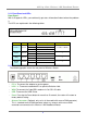
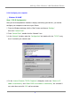
2.1.1 Front Panel and LEDs
Front Panel :
With its Diagnostic LEDs, you could easily get status information find out where the problem
is.
The LEDs are explained in the following tables.
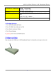
2.1.2 Rear Panel
The following graphic shows the rear panel of Wireless Router.
‧ DC In: To connect the adapter to receive power.
‧ LAN 1~4: To connect networked PC or uplink to Switch or Hub.
‧ WAN: To connect the Cabel/DSL modem via Cat.5 RJ-45 cable.
‧ USB: To connect the USB Printer
‧ Reset: Pressing the Reset button for more than 5 seconds, the router will restore to
factory default setting.
‧ Antenna Connector: (Optional, only exists in the model with reverse SMA connector)
This is standard reverse SMA connector where any antenna with reverse SMA
connector can connect to this Wireless LAN Broadband Router.
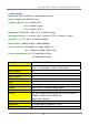
Label Color Status Meaning Number of LEDs
On Link On
Blinking Activity
Off Link Off
On Power ON
Off Power OFF
On Work mode fail
Off Normal work mode
On Link On
Off Link Off
Yellow 1
1Power Green
WLAN
(Link)
Diag Green 1
Link/Act. Green 4 x LAN,1 x WAN