
Operation Manual


Page
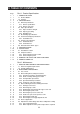
Part 5: Appendix
5 - 1 1. TECHNICAL REFERENCE
5 - 1 1.1 About the Paper Feed Section
5 - 1 1.1.1 Paper feed functions
5 - 2 1.1.2 Structure of the paper feed components
5 - 3 1.1.3 Advanced paper feed function
5 - 3 1.1.4 Paper feed retry function
5 - 3 1.1.5 The print start position adjustment retry function
5 - 3 1.1.6 The form alignment function
5 - 4 1.2 About the Purge Unit
5 - 4 1.2.1 The capping and cleaning functions of the purge unit
5 - 5 1.2.2 Purge unit paper feed motor drive switching function
5 - 5 1.2.3 Purge unit structure and functions
5 - 7 1.3 About the Electrical Section
5 - 7 1.3.1 Electrical section block diagram
5 - 7 1.3.2 Power line block diagram
5 - 8 1.3.3 USB interface
5 - 9 1.3.4 Automatic interface switching function
5 - 9 1.3.5 Detection functions with sensors
5 - 10 1.4 About the BJ Cartridge
5 - 10 1.4.1 BJ cartridge structure
5 - 10 1.4.2 BJ cartridge print drive control
5 - 10 1.4.3 BJ cartridge identification
5 - 11 1.4.4 List of printing modes
5 - 12 1.5 About the Scanner Cartridge
5 - 12 1.5.1 Scanner block diagram and the data flow
5 - 13 1.5.2 Scan modes
5 - 14 1.5.3 Image gradation and bit data size
5 - 14 1.5.4 Scanner cartridge detection
5 - 14 1.5.5 Calibration operation based on the white calibration sheet
5 - 14 1.5.6 Scanning time and data size (reference)
5 - 15 2. CONNECTORS AND PIN LAYOUT
5 - 15 2.1 Control Board
5 - 19 2.2 Carriage Board
5 - 20 2.3 BJ Cartridge
5 - 21 2.4 Scanner Cartridge (Optional)
5 - 22 2.5 AC Adapter
5 - 22 2.6 DC Power Supply Cable
5 - 23 2.7 Carriage Motor
5 - 23 2.8 Paper Feed Motor
5 - 23 2.9 Ink Sensor
IV