Cannon FREESTANDING MODELS CANTFS-03-NG CANTFS-03-LP USER INSTRUCTIONS Cannon CANTERBURY INSTALLATION INSTRUCTIONS Part No: F2902 Revision (C) - 2008 SERVICE INSTRUCTIONS This heater is approved for use with Natural and Propane gases.
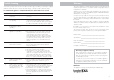
Contents Contents 2 Warranty 3 9. No gas to burner. • The gas valve should open at the same time as the igniter sparks. If there is no gas to the burner when this occurs check the solenoid coils for continuity. • Check that the gas pressure is present at the test point when the spark is being generated. • Check that there is gas to the inlet of the gas control. 10. Appliance lights but goes into lockout. • Test the flame for correct ionisation signal.
Trouble-shooting Warranty To check the operation of the electronic (module) controller (Type 537 ABC) you will require a digital multimeter with the functions to measure AC/DC voltage, continuity, resistance and micro-amps. It is critical that the appliance is earthed and that the active and neutrals are not reversed. Item No Check Action 1. No ignition when appliance is turned on. • Check 240 volts power to heater in incoming plug connector. 2. Power present but appliance not operating.
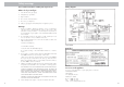
Safety warnings Please read this manual before installing and using the heater. Wiring diagram What to do if you smell gas 1. Turn OFF the main gas supply. 2. Extinguish any open flame. 3. Open windows. 4. Do not touch electrical switches. 5. Do not use your telephone. 6. Call your gas supplier immediately from a neighbour’s phone. Warnings 1. Improper installation, adjustment, alteration, service or maintenance can cause injury or property damage.
Service instructions General 1. Service work to be carried out by a licensed service person only. 2. Unplug from wall socket. 3. Always shut off the gas supply and ensure that the heater is cool before commencing any service operations. 4. Always check for gas soundness after servicing. Access to components Do not place articles on or against this appliance. Do not use or store flammable materials near this appliance. 8. This heater is not intended for use in a marine environment. 9.
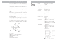
User instructions Flue installation - Alternative double skin flue kit Operating instructions 1. Plug the power cord into the wall socket and turn on the power to the heater, see figure 1. Use of an extension cord is not recommended. 1 2. For control lay-out refer to figure 2 2 3. To turn heater on press switch to POWER ON position. There is a 5 second delay before the burner ignites. At this setting the burner is on LOW and the fan speed is on LOW. Refer figure 3.
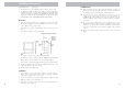
Flue installation - Alternative double skin flue kit Alternative double skin flue installation This heater is a flued appliance. It must be properly connected to a flue system in accordance with the latest edition of the Gas Installation Code, AS 5601. 5. To increase the fan speed to MED, press switch for MED setting. Refer figure 5. If elbows are required, we recommend 45° only and no more than two in the total flue run. There should also be a minimum of 250mm straight flue section in between bends.
Flue installation - Standard flue kit Flame characteristics The heater flame should be stable, no lifting from the burner and the logs should glow after approximately 15 minutes operation on HIGH setting. The heater is a fuel effect unit and is designed to operate with luminous flames and may exhibit slight carbon deposits on the logs. If there is any excess carbon build-up on the logs, or the burner flame is unstable, contact Sampford IXL in your state. (See phone contact on page 21.
Flue installation - Standard flue kit This heater is a flued appliance. It must be properly connected to a flue system in accordance with the latest edition of the Gas Installation Code, AS 5601/AG 601. If elbows are required, we recommend 45° only and no more than two in the total flue run, there should also be a minimum of 250mm straight flue section in between bends.. If practical, locate the heater in a position to minimise the need for elbows. There must be at least 1.
Installation instructions Overall dimensions: Refer fig. 8. 1. This appliance is to be installed by a licensed service person only. 2. This appliance shall be installed in accordance with the manufacturer’s installation instructions, local gas fitting regulations, municipal building codes, electrical wiring regulations, and AS5601 the Australian Standard for gas installations. Refer also AS5601 for gas pipe sizing tables.
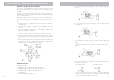
Important: 18. Switch the top two control buttons to “Full On” position as indicated in figure 23(a) and using a ring spanner, as per figure 23(b), adjust the To achieve the correct pressure to 0.75 kPa for Natural gas or 2.65 kPa for LPG. (Turn clockvisual flame effect: wise to increase pressure and anticlockwise to decrease pressure). On Propane the gas pressure must be set at 2.65 kPa with burner operating on maximum setting. On Natural Gas the gas pressure must be set at 0.75kPa. 11 12 23 19.
Position the four individually numbered logs in the following order on the burner head as shown in figures 15 - 18. The male locating pins in the burner head must engage with corresponding holes in the individual logs. If the flame is unstable: ❍ Check that the burner is located correctly. ❍ Check that the glass front is located correctly and is against the sealing rope. ❍ Check that the gas pressure is correctly adjusted. a) Place log No.
Position the four individually numbered logs in the following order on the burner head as shown in figures 15 - 18. The male locating pins in the burner head must engage with corresponding holes in the individual logs. If the flame is unstable: ❍ Check that the burner is located correctly. ❍ Check that the glass front is located correctly and is against the sealing rope. ❍ Check that the gas pressure is correctly adjusted. a) Place log No.
Important: 18. Switch the top two control buttons to “Full On” position as indicated in figure 23(a) and using a ring spanner, as per figure 23(b), adjust the To achieve the correct pressure to 0.75 kPa for Natural gas or 2.65 kPa for LPG. (Turn clockvisual flame effect: wise to increase pressure and anticlockwise to decrease pressure). On Propane the gas pressure must be set at 2.65 kPa with burner operating on maximum setting. On Natural Gas the gas pressure must be set at 0.75kPa. 11 12 23 19.
Installation instructions Overall dimensions: Refer fig. 8. 1. This appliance is to be installed by a licensed service person only. 2. This appliance shall be installed in accordance with the manufacturer’s installation instructions, local gas fitting regulations, municipal building codes, electrical wiring regulations, and AS5601 the Australian Standard for gas installations. Refer also AS5601 for gas pipe sizing tables.
Flue installation - Standard flue kit This heater is a flued appliance. It must be properly connected to a flue system in accordance with the latest edition of the Gas Installation Code, AS 5601/AG 601. If elbows are required, we recommend 45° only and no more than two in the total flue run, there should also be a minimum of 250mm straight flue section in between bends.. If practical, locate the heater in a position to minimise the need for elbows. There must be at least 1.
Flue installation - Standard flue kit Flame characteristics The heater flame should be stable, no lifting from the burner and the logs should glow after approximately 15 minutes operation on HIGH setting. The heater is a fuel effect unit and is designed to operate with luminous flames and may exhibit slight carbon deposits on the logs. If there is any excess carbon build-up on the logs, or the burner flame is unstable, contact Sampford IXL in your state. (See phone contact on page 21.
Flue installation - Alternative double skin flue kit Alternative double skin flue installation This heater is a flued appliance. It must be properly connected to a flue system in accordance with the latest edition of the Gas Installation Code, AS 5601. 5. To increase the fan speed to MED, press switch for MED setting. Refer figure 5. If elbows are required, we recommend 45° only and no more than two in the total flue run. There should also be a minimum of 250mm straight flue section in between bends.
User instructions Flue installation - Alternative double skin flue kit Operating instructions 1. Plug the power cord into the wall socket and turn on the power to the heater, see figure 1. Use of an extension cord is not recommended. 1 2. For control lay-out refer to figure 2 2 3. To turn heater on press switch to POWER ON position. There is a 5 second delay before the burner ignites. At this setting the burner is on LOW and the fan speed is on LOW. Refer figure 3.
Service instructions General 1. Service work to be carried out by a licensed service person only. 2. Unplug from wall socket. 3. Always shut off the gas supply and ensure that the heater is cool before commencing any service operations. 4. Always check for gas soundness after servicing. Access to components Do not place articles on or against this appliance. Do not use or store flammable materials near this appliance. 8. This heater is not intended for use in a marine environment. 9.
Safety warnings Please read this manual before installing and using the heater. Wiring diagram What to do if you smell gas 1. Turn OFF the main gas supply. 2. Extinguish any open flame. 3. Open windows. 4. Do not touch electrical switches. 5. Do not use your telephone. 6. Call your gas supplier immediately from a neighbour’s phone. Warnings 1. Improper installation, adjustment, alteration, service or maintenance can cause injury or property damage.
Trouble-shooting Warranty To check the operation of the electronic (module) controller (Type 537 ABC) you will require a digital multimeter with the functions to measure AC/DC voltage, continuity, resistance and micro-amps. It is critical that the appliance is earthed and that the active and neutrals are not reversed. Item No Check Action 1. No ignition when appliance is turned on. • Check 240 volts power to heater in incoming plug connector. 2. Power present but appliance not operating.
Contents Contents 2 Warranty 3 9. No gas to burner. • The gas valve should open at the same time as the igniter sparks. If there is no gas to the burner when this occurs check the solenoid coils for continuity. • Check that the gas pressure is present at the test point when the spark is being generated. • Check that there is gas to the inlet of the gas control. 10. Appliance lights but goes into lockout. • Test the flame for correct ionisation signal.
Cannon FREESTANDING MODELS CANTFS-03-NG CANTFS-03-LP USER INSTRUCTIONS Cannon CANTERBURY INSTALLATION INSTRUCTIONS Part No: F2902 Revision (C) - 2008 SERVICE INSTRUCTIONS This heater is approved for use with Natural and Propane gases.