
Technical information


2-86
CHAPTER 2 NEW FUNCTIONS
COPYRIGHT
©
2001 CANON INC. 2000 2000 2000 2000 CANON CLC5000 REV.0 JAN. 2001
5 Pickup/Feed System
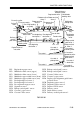
5.1 Outline of the Pickup/Feed System
• The major difference is the higher copying speed (from 30 to 50 cpm; A4, Direct).
• The pickup assembly is based on that of the CLC1100.
The feed system, on the other hand, is identical to that of the CLC1000.
The machine uses the center reference method, in which paper is moved in the middle of
the pickup/ feed path.
To accommodate the increase in the copying speed, the feed speed to the registration
roller has been increased to 400 mm/sec (in relation to the process speed of 200 mm/sec).
The pickup system consists of the following: cassette 1, cassette 2, multifeeder, and hold-
ing tray (duplex unit). (For the paper deck, see 8. “Paper Deck.”)
The paper picked up from the cassette or the multifeeder is controlled so that the leading
edge will match the leading edge of the image on the photosensitive drum, and is sent to the
transfer belt.
When the paper arrives at the transfer belt, the charge from the transfer blade causes it to
be attracted to the transfer belt; transfer of the first color (cyan) takes place to coincide with
static attraction.
When all four colors have been transferred, the paper is then moved to the delivery tray
through the separation, feeding, and fixing assemblies (F02-502-01).
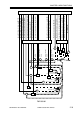
The CPU on the machine’s DC controller PCB generates the image leading edge signal
(ITOP) as soon as the registration roller turns to initiate reading of image data from the IP
memory PCB.